Circuit board printing machine

A technology for printing machines and circuit boards, which is applied to printing machines, rotary printing machines, screen printing machines, etc., and can solve problems such as sticking, affecting the welding effect of components, unevenness, etc.

Inactive Publication Date: 2015-12-02
SUZHOU ENOUXI INTELLIGENT TECH CO LTD
View PDF10 Cites 8 Cited by
  • Summary
  • Abstract
  • Description
  • Claims
  • Application Information

AI Technical Summary

Problems solved by technology

When the scraper on the traditional printing machine is working, the scraper presses the solder paste or red glue at 45° and moves back and forth. Since the scraper is only provided with a slope inclined at 45° on one side, use the slope to press the solder paste or red glue forward. Move, and when moving backward, because the solder paste or red glue is not detached from the slope, the scraper will stick to part of the solder paste or red glue and move backward, so that it will stick to the scraped pad, and the scraper will stick to it again When moving forward for the second scraping, the part without solder paste or red glue and the part with solder paste or red glue will be uneven, which will affect the soldering effect of components

Method used


Image

  • Circuit board printing machine
  • Circuit board printing machine

Examples


Embodiment Construction

[0015] The specific embodiments of the present invention will be described in further detail below with reference to the accompanying drawings and embodiments. The following examples are intended to illustrate the present invention, but not to limit the scope of the present invention.

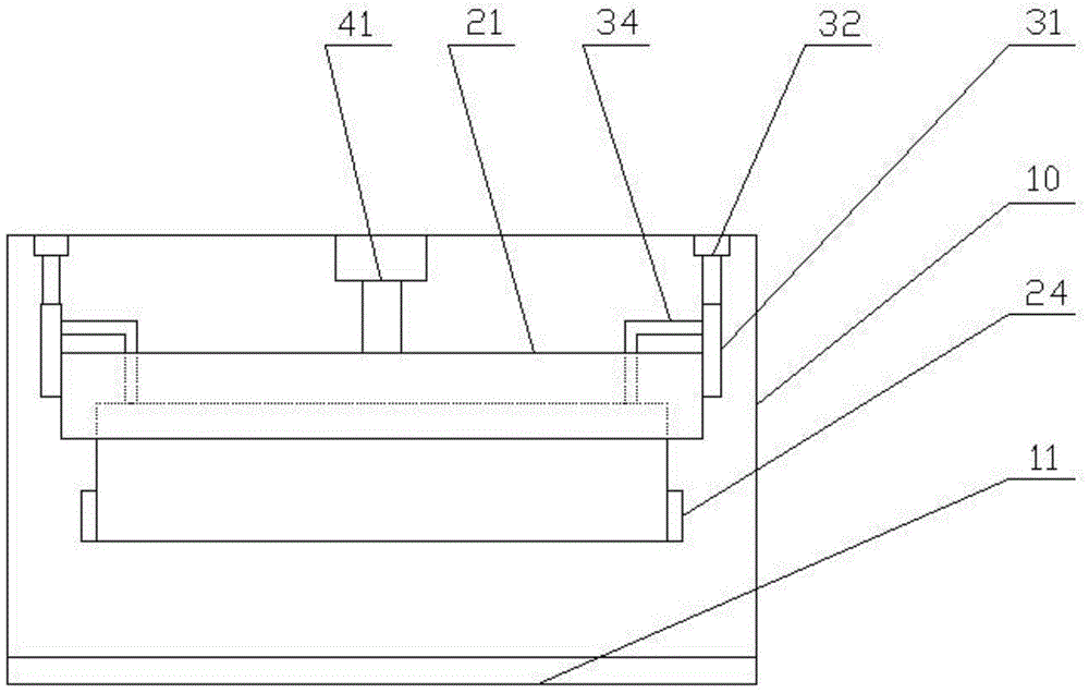
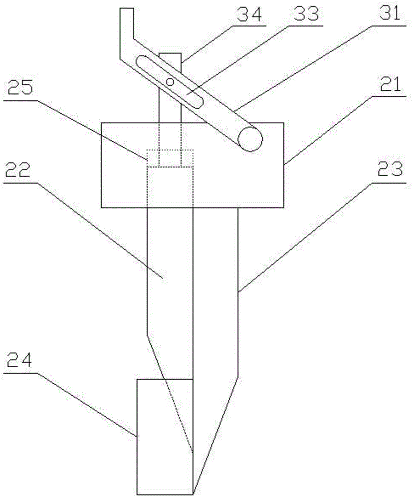
[0016] see figure 1 and figure 2 , a circuit board printing machine according to a preferred embodiment of the present invention includes a frame 10 with a worktable 11, the frame 10 is provided with a squeegee assembly that moves longitudinally and horizontally relative to the frame 10, and the squeegee assembly includes The knife holder 21 is provided with two scrapers with their backs attached to each other, which are a first scraper 22 and a second scraper 23 respectively. Both sides of the knife holder 21 are provided with a longitudinal direction for driving the first scraper 22 relative to the second scraper 23 As for the moving first driving mechanism, the frame 10 is provided with a...


PUM


Abstract

The invention relates to a circuit board printing machine which comprises a rack provided with a workbench. A scraper assembly which moves relative to the rack in the longitudinal direction and in the horizontal direction is arranged on the rack; the scraper assembly comprises a scraper rack; two scrapers including the first scraper and the second scraper are arranged on the scraper rack, and the back side of the first scraper and the back side of the second scraper are attached to each other; the two sides of the scraper rack are provided with a first driving mechanism used for driving the first scraper to move relative to the second scraper in the longitudinal direction; a second driving mechanism used for driving the scrapers to move in the longitudinal direction and in the horizontal direction is arranged on the rack. According to the circuit board printing machine, the first scraper and the second scraper are arranged, the back side of the first scraper and the back side of the second scraper are attached to each other, and the first scraper is made to move relative to the second scraper in the longitudinal direction, and accordingly solder paste or red glue adhering to the second scraper can be scraped off through the first scraper, the solder paste or the red glue is prevented from adhering to a printed circuit board when the scrapers retract, the circuit board is printed uniformly, and therefore the welding effect of components and parts is guaranteed.

Description

technical field [0001] The invention relates to the field of surface mount technology (SMT), in particular to a printing machine for printing solder paste or red glue on a printed circuit board. Background technique [0002] When the circuit board printing machine is working, it is first necessary to print the solder paste or red glue on the pads of the circuit board at a 45° angle with a scraper to prepare for the soldering of the components. When the squeegee on the traditional printing press is working, the squeegee presses the solder paste or red glue at 45° and moves back and forth. Since the squeegee is only set on one side with a 45° inclined slope, the slope is used to press the solder paste or red glue forward. When moving backwards, since the solder paste or red glue is not detached from the inclined surface, the scraper will stick to part of the solder paste or red glue and move backwards, so that it will stick to the scraped pads. When moving forward for the sec...

Claims


Application Information

Patent Timeline
Patent Type & Authority Applications(China)
IPC IPC(8): B41F15/46
Inventor 杨文杰
Owner SUZHOU ENOUXI INTELLIGENT TECH CO LTD
Why Eureka
Try Eureka