LED light-emitting device and manufacturing method thereof
A technology of light-emitting devices and LED chips, which is applied to semiconductor devices, electrical components, circuits, etc., can solve problems such as low light efficiency and color rendering index, increase high refractive index, and affect light-emitting performance, so as to improve light efficiency and reduce Light refraction, the effect of improving the light output rate
- Summary
- Abstract
- Description
- Claims
- Application Information
AI Technical Summary
Problems solved by technology
Method used
Image
Examples
preparation example Construction
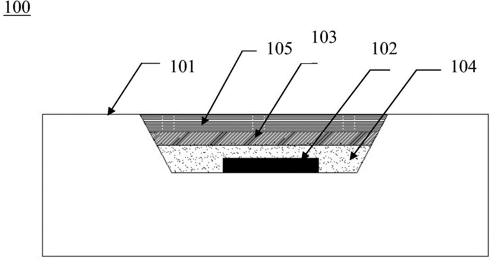
[0099] A method for preparing an LED light-emitting device, characterized in that it comprises the following steps:
[0100] (1) Fixing the LED chip on the substrate;
[0101] (2) The refractive index buffer layer formed by uniformly mixing the fine powder filler with the refractive index between the LED chip and the silica gel and the silica gel is arranged on the LED chip in an adhesive manner;
[0102] (3) A resin layer is provided on the refractive index buffer layer.
[0103] According to a preferred specific embodiment, the above-mentioned preparation method further includes the following steps: (4) disposing a non-uniform luminescent powder layer on or within the resin layer in which the phosphor powder is non-uniformly distributed. The non-uniform luminescent powder layer 105 includes at least two layers of luminescent powder layered on top of each other and composed of phosphor powders of different types, or at least two layers of luminescent powder layered on top of...
Embodiment 1
[0105] Embodiment 1: the preparation of refractive index buffer layer
[0106] The preparation method of the refractive index buffer layer is to obtain the refractive index buffer layer by uniformly mixing 0.01% to 50% by weight of powdered filler with silica gel, or simply by filling the groove on the substrate for fixing the LED chip with powder The refractive index buffer layer is obtained by using the filling material. The light transmittance of the powder filler is greater than 50%, the refractive index is in the range of 1.05-2.5, and the particle size is in the range of 0.1 μm-200 μm. Powdered fillers are glass beads, fused quartz, fluorite and / or crown glass. See Table 3 for the refractive index of the above materials and the mixing ratio with silica gel.
[0107] table 3
[0108] substance Refractive index The mixing ratio(%) Fused Quartz 1.45843 5 fluorite 1.43381 15 crown glass 1.51110~1.51630 10
[0109] Table 4(a) and Tab...
Embodiment 2
[0116] Example 2: Non-uniform luminescent powder film prepared using the principle of free sedimentation
[0117] Using the principle of sedimentation, phosphors with different specific gravity have different sedimentation speeds in silica gel. Since the silica gel has a certain viscosity, the phosphor is subjected to gravity and the buoyancy of the silica gel in the silica gel, and the phosphor particles have a downward acceleration under the action of the two forces. Since the luminescent film has a certain thickness, the settling time of the fluorescent powder in the silica gel can be estimated.
[0118] Referring to Figure 3(a) and Figure 3(b), circles of different sizes represent phosphors of different particle sizes. It should be noted here that the particle size of the phosphor is a continuously changing value, even for the same phosphor particle size They are not the same, but there is a division. According to the statistical point of view, we take the middle value, s...
PUM
| Property | Measurement | Unit |
|---|---|---|
| Granularity | aaaaa | aaaaa |
Abstract
Description
Claims
Application Information
 - R&D Engineer
- R&D Manager
- IP Professional
- Industry Leading Data Capabilities
- Powerful AI technology
- Patent DNA Extraction
Browse by: Latest US Patents, China's latest patents, Technical Efficacy Thesaurus, Application Domain, Technology Topic, Popular Technical Reports.
© 2024 PatSnap. All rights reserved.Legal|Privacy policy|Modern Slavery Act Transparency Statement|Sitemap|About US| Contact US: help@patsnap.com


