A shift register, driving method, and gate driving circuit

A shift register and electrode technology are applied in the fields of gate drive circuits, shift registers and drive methods, and can solve the problem of large layout area of ​​gate drive circuits, increased wiring complexity of upper and lower shift registers, and disadvantage of narrow frame design. and other problems to achieve the effect of reducing the frame, reducing the area, and simplifying the wiring

Active Publication Date: 2017-08-22
WUHAN TIANMA MICRO ELECTRONICS CO LTD +1
View PDF8 Cites 0 Cited by
  • Summary
  • Abstract
  • Description
  • Claims
  • Application Information

AI Technical Summary

Problems solved by technology

like figure 1 As shown, the shift register includes a shift register unit 11 and an inverting unit 12, and the trigger signal input by the input terminal IN of the shift register unit 11 is a low level signal, that is, the shift register unit 11 is triggered by a low level, In order to realize the function of the gate drive circuit, it is necessary to arrange three cascaded inverter units 12 at the rear end of the shift register unit 11. Therefore, the number of transistors and capacitors used in the gate drive circuit is relatively large, resulting in The layout area occupied by the driving circuit is relatively large, which is not conducive to the narrow border design
More importantly, the front-stage shift register is transmitted to the subsequent-stage shift register through a separately set NEXT signal, which increases the complexity of wiring between the upper and lower-stage shift registers, and is also not conducive to narrow bezel design

Method used


Image

  • A shift register, driving method, and gate driving circuit
  • A shift register, driving method, and gate driving circuit
  • A shift register, driving method, and gate driving circuit

Examples


Embodiment Construction

[0040] In order to make the purpose, technical solutions and advantages of the present invention clearer, the technical solutions of the present invention will be clearly and completely described through implementation with reference to the accompanying drawings of the embodiments of the present invention. Obviously, the described embodiments are part of the present invention Examples, not all examples. Based on the embodiments of the present invention, all other embodiments obtained by persons of ordinary skill in the art without making creative efforts belong to the protection scope of the present invention.

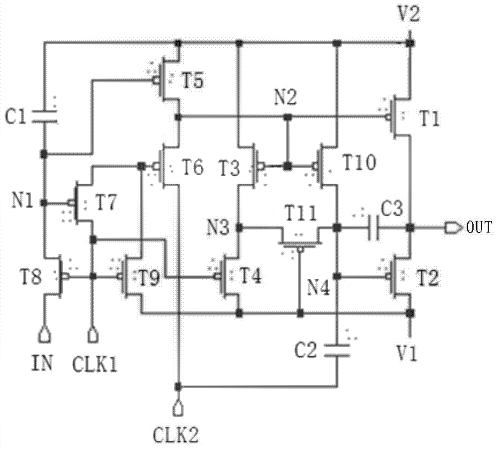
[0041] refer to figure 2 As shown, it is a circuit structure diagram of a shift register provided by an embodiment of the present invention. The shift register includes: a first transistor T1, a second transistor T2, a third transistor T3, a fourth transistor T4, a fifth transistor T5, a sixth transistor T6, a seventh transistor T7, an eighth transistor T8, and a nin...


PUM


Abstract

The invention provides a shift register, a driving method, and a gate driving circuit. The shift register includes: a first transistor, a second transistor, a third transistor, a fourth transistor, a fifth transistor, a sixth transistor, a seventh transistor, an eighth transistor, a ninth transistor, a first capacitor, and a second capacitor, And a trigger signal input terminal, a first clock signal terminal, a second clock signal terminal, a first level signal terminal, a second level signal terminal and an output terminal, the trigger signal input terminal receives a high level trigger signal, the The output end of the shift register outputs a high level signal. The shift register occupies a small layout area, which is beneficial to reducing the frame of the display panel.

Description

technical field [0001] The invention relates to the field of display technology, in particular to a shift register, a driving method, and a gate driving circuit. Background technique [0002] The rapid development of liquid crystal display technology forces liquid crystal panel manufacturers to consider not only the performance and cost of liquid crystal panels, but also the aesthetics of liquid crystal panels. In order to facilitate the design of the narrow frame of the liquid crystal panel, the relevant technicians arrange the gate drive circuit on the edge of the liquid crystal panel, and the gate drive circuit includes a plurality of shift registers connected in series. [0003] figure 1 It is a circuit structure diagram of a relatively common shift register in the prior art. like figure 1 As shown, the shift register includes a shift register unit 11 and an inverting unit 12, and the trigger signal input by the input terminal IN of the shift register unit 11 is a low...

Claims


Application Information

Patent Timeline
Patent Type & Authority Patents(China)
IPC IPC(8): G09G3/36G11C19/28
Inventor 吴桐钱栋杨明玲
Owner WUHAN TIANMA MICRO ELECTRONICS CO LTD
Why Eureka
Try Eureka