Construction protection structure under overhead high voltage line and its application method

A technology of protective structure and application method, applied in the direction of anti-theft alarms, instruments, alarms, etc., can solve the problems of high alertness, constant attention, increased construction period, and increased construction cost, and achieves short erection time, low investment cost, The effect of simplified protective measures

Active Publication Date: 2018-09-07
MUNICIPAL ENVIRONMENTAL PROTECTION ENG CO LTD OF CREC SHANGHAI GRP +1
View PDF8 Cites 0 Cited by
  • Summary
  • Abstract
  • Description
  • Claims
  • Application Information

AI Technical Summary

Problems solved by technology

[0003] At present, there are generally two types of protective structures. The first one is such as Figure 4 As shown, a height limit warning line 6 is hung between the high-voltage line columns 2 where the overhead high-voltage line 1 is suspended, and then a warning ball 7 is hung on the height limit warning line 6. The warning ball 7 is used to remind the operator driving the construction equipment to limit the height The warning line 6 exists, but the operator still needs to observe the height limit warning line 6 with the naked eye to avoid touching the overhead high-voltage line 1 or entering the dangerous area around the high-voltage line 1. The operator is highly vigilant and always pays attention to the existence of the height limit warning line 6
The second is as Figure 5 As shown, the protective scaffolding 8 is directly erected on the periphery of the construction area 9, so that the construction is completed in the protective scaffolding 8, and the construction equipment is prevented from touching high-voltage lines. Although the safety protection effect is better, the construction of the protective scaffolding 8 will increase the construction cost. Height increase and construction cycle growth

Method used


Image

  • Construction protection structure under overhead high voltage line and its application method
  • Construction protection structure under overhead high voltage line and its application method
  • Construction protection structure under overhead high voltage line and its application method

Examples


Embodiment

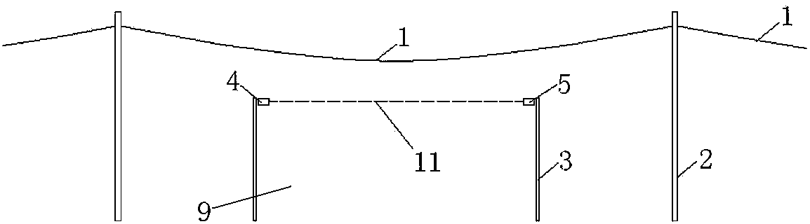
[0023] Example: such as figure 1 As shown, the overhead high-voltage line 1 is suspended on two high-voltage line columns 2 , and the construction area 9 is located between the two high-voltage line columns 2 . There are a variety of construction equipment (such as cranes) in the construction area 9, and the construction equipment has a lifting working part (such as the boom of the crane), and in order to prevent the lifting working part of the construction equipment from touching the overhead high-voltage line 1, in the overhead A safety boundary 10 is set between the high voltage line 1 and the construction area 9 .

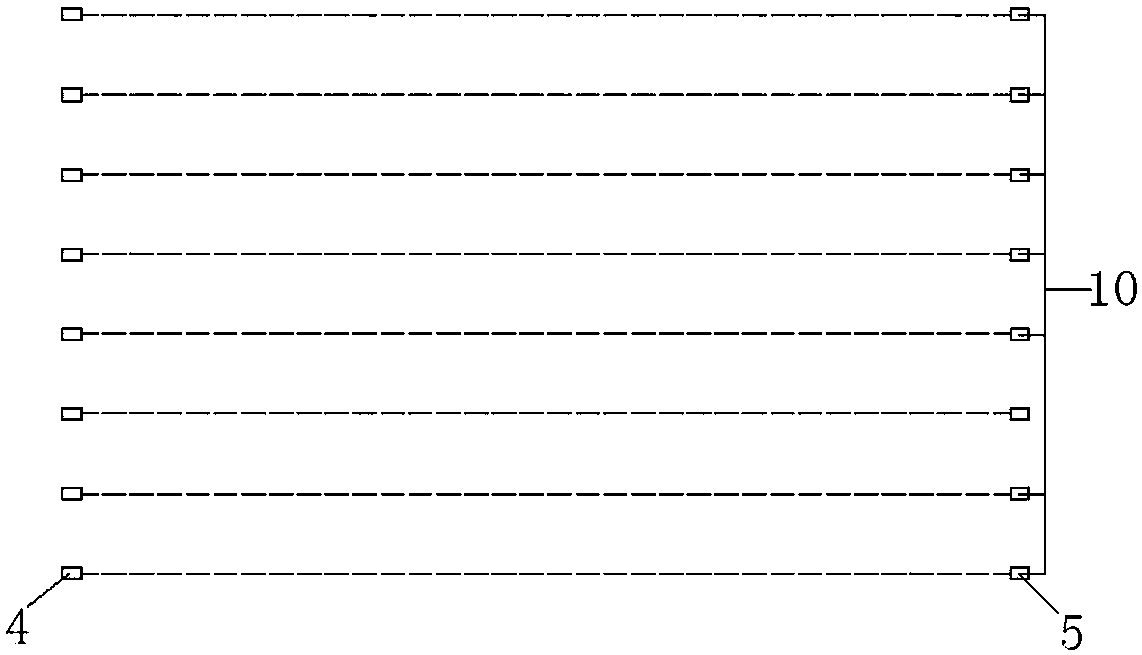
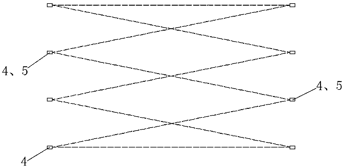
[0024] Such as figure 1 As shown, the safety boundary 10 includes several columns 3 , and several columns 3 are arranged on both sides of the construction area 9 at intervals along the parallel direction of the high-voltage line columns 2 (the direction perpendicular to the direction of the overhead high-voltage line 1 ). The distance between the two opposi...


PUM


Abstract

The invention relates to a construction protective structure under overhead high-tension lines and an application method of the structure, and belongs to the field of pavement construction protection. The structure is characterized in that a safe boundary is arranged between the overhead high-tension lines and a construction area, the safe boundary is formed by infrared detector groups and columns, the columns are fixedly arranged at the two sides of the construction area respectively, each infrared detector group comprises an emitter and a receiver, the emitter and the receiver are fixedly mounted on the two columns opposite to each other, the position of the emitter corresponds to that of the receiver to form an infrared induction line, and the positions of the emitters are in one to one correspondence with those of the receives to form a region of the infrared induction lines. The construction protective structure has the advantages that convenience is provided for construction, protection measures are simplified and the structure is suitable for popularization.

Description

technical field [0001] The invention relates to the field of road surface construction protection, in particular to a construction protection structure under an overhead high-voltage line and an application method thereof. Background technique [0002] When carrying out road construction on the road below the overhead high-voltage line, in order to prevent road construction equipment, such as cranes, from touching the overhead high-voltage line and causing safety hazards, a protective structure is usually erected between the construction equipment and the overhead high-voltage line to ensure safety. [0003] At present, there are generally two types of protective structures. The first one is such as Figure 4 As shown, a height limit warning line 6 is hung between the high-voltage line columns 2 where the overhead high-voltage line 1 is suspended, and then a warning ball 7 is hung on the height limit warning line 6. The warning ball 7 is used to remind the operator driving th...

Claims


Application Information

Patent Timeline
Patent Type & Authority Patents(China)
IPC IPC(8): G08B13/183
CPCG08B13/183
Inventor 陈辉王勇刘学明王冬冬胡洋
Owner MUNICIPAL ENVIRONMENTAL PROTECTION ENG CO LTD OF CREC SHANGHAI GRP
Why Eureka
Try Eureka