Device, method and electronic device for segmenting cohesive objects in images
An object segmentation and image-based technology, applied in the information field, can solve the problems of bacteria count errors, bacteria sticking or overlapping, and inseparability
- Summary
- Abstract
- Description
- Claims
- Application Information
AI Technical Summary
Problems solved by technology
Method used
Image

Examples
Embodiment 1
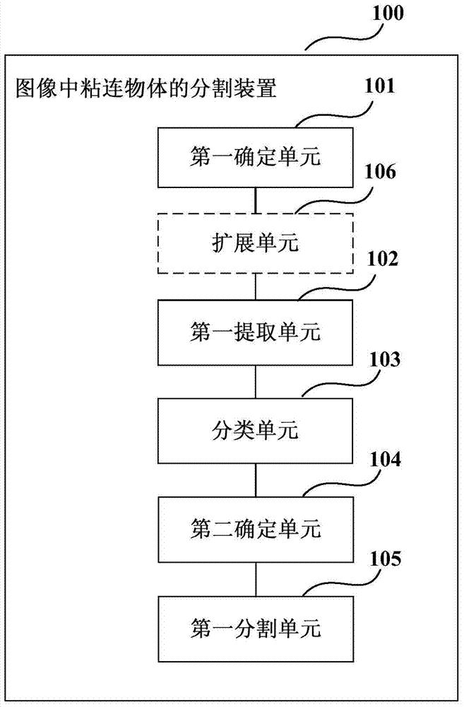
[0025] figure 1 It is a schematic structural diagram of the segmentation device for sticky objects in an image according to Embodiment 1 of the present invention. like figure 1 As shown, the device 100 includes: a first determination unit 101, a first extraction unit 102, a classification unit 103, a second determination unit 104, and a first segmentation unit 105, wherein,
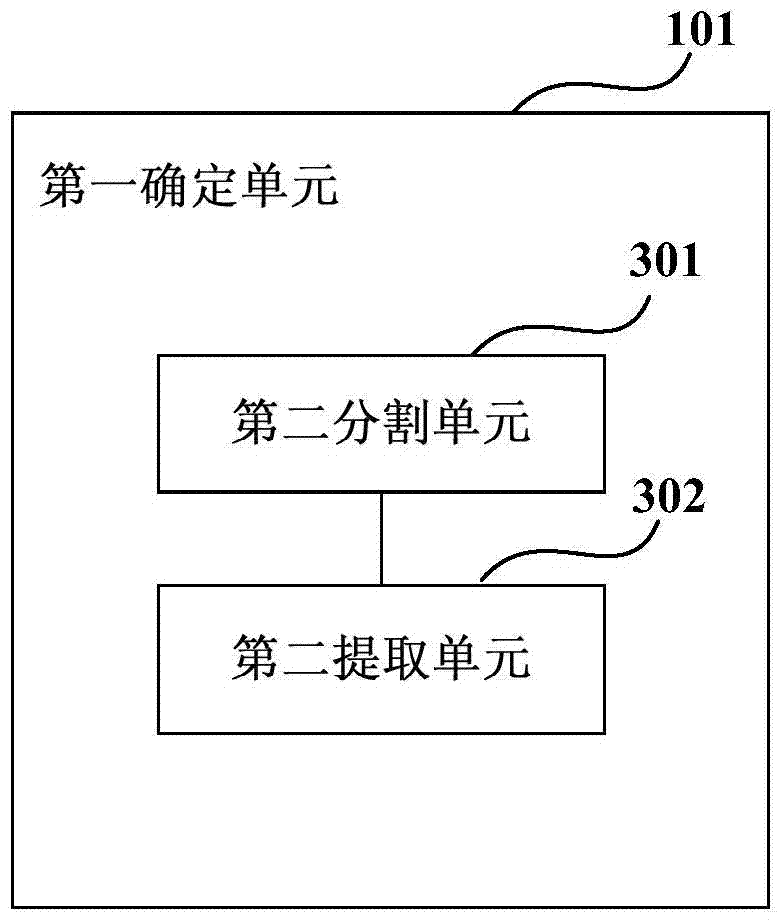
[0026] The first determining unit 101 is configured to determine candidate segmentation boundaries of cohesive objects in the image;
[0027] The first extraction unit 102 is used to extract the features of all candidate segmentation boundaries;
[0028] The classification unit 103 is used to classify all candidate segmentation boundaries according to the extracted features;
[0029] The second determining unit 104 is configured to determine the dividing line according to the classification result;
[0030] The first segmentation unit 105 is configured to segment the adhered object based on the segmen...
Embodiment 2
[0056] An embodiment of the present invention provides an electronic device, which includes the device for segmenting a cohesive object in an image as described in Embodiment 1.
[0057] Figure 7 It is a schematic block diagram of the system configuration of the electronic device 700 according to Embodiment 2 of the present invention. like Figure 7 As shown, the electronic device 700 may include a central processing unit 701 and a memory 702; the memory 702 is coupled to the central processing unit 701. This diagram is exemplary; other types of structures may also be used in addition to or in place of this structure, for telecommunications or other functions.
[0058] like Figure 7 As shown, the electronic device 700 may further include: a camera unit 703 , a communication module 704 , an input unit 705 , a display 706 , and a power supply 707 . Wherein, the camera unit 703 inputs the captured image to the memory 702 for storage.
[0059] In one embodiment, the functio...
Embodiment 3
[0072] Figure 8 It is a flow chart of the method for segmenting cohesive objects in images according to Embodiment 3 of the present invention, corresponding to the device for segmenting cohesive objects in images in Embodiment 1. like Figure 8 As shown, the method includes:
[0073] Step 801: Determine the candidate segmentation boundaries of cohesive objects in the image;
[0074] Step 802: extracting features of all candidate segmentation boundaries;
[0075] Step 803: classify all candidate segmentation boundaries according to the extracted features;
[0076] Step 804: Determine the dividing line according to the classification result;
[0077] Step 805: Segment the glued object based on the segmentation line.
[0078] In this embodiment, the method of determining candidate segmentation boundaries, the method of extracting features, the method of classifying according to the extracted features, the method of determining the segmentation line according to the classifi...
PUM
 Abstract
Description
Claims
Application Information
 - R&D
- Intellectual Property
- Life Sciences
- Materials
- Tech Scout
- Unparalleled Data Quality
- Higher Quality Content
- 60% Fewer Hallucinations
Browse by: Latest US Patents, China's latest patents, Technical Efficacy Thesaurus, Application Domain, Technology Topic, Popular Technical Reports.
© 2025 PatSnap. All rights reserved.Legal|Privacy policy|Modern Slavery Act Transparency Statement|Sitemap|About US| Contact US: help@patsnap.com