Prefabricated formed butterfly introduction optical cable, manufacture method thereof and wiring method thereof
A lead-in optical cable and butterfly technology, which is applied in the field of prefabricated-end butterfly lead-in cable and its preparation and wiring, to achieve the effects of improved yield and production efficiency, convenient wiring, and reduced wiring area
- Summary
- Abstract
- Description
- Claims
- Application Information
AI Technical Summary
Problems solved by technology
Method used
Image
Examples
Embodiment 1
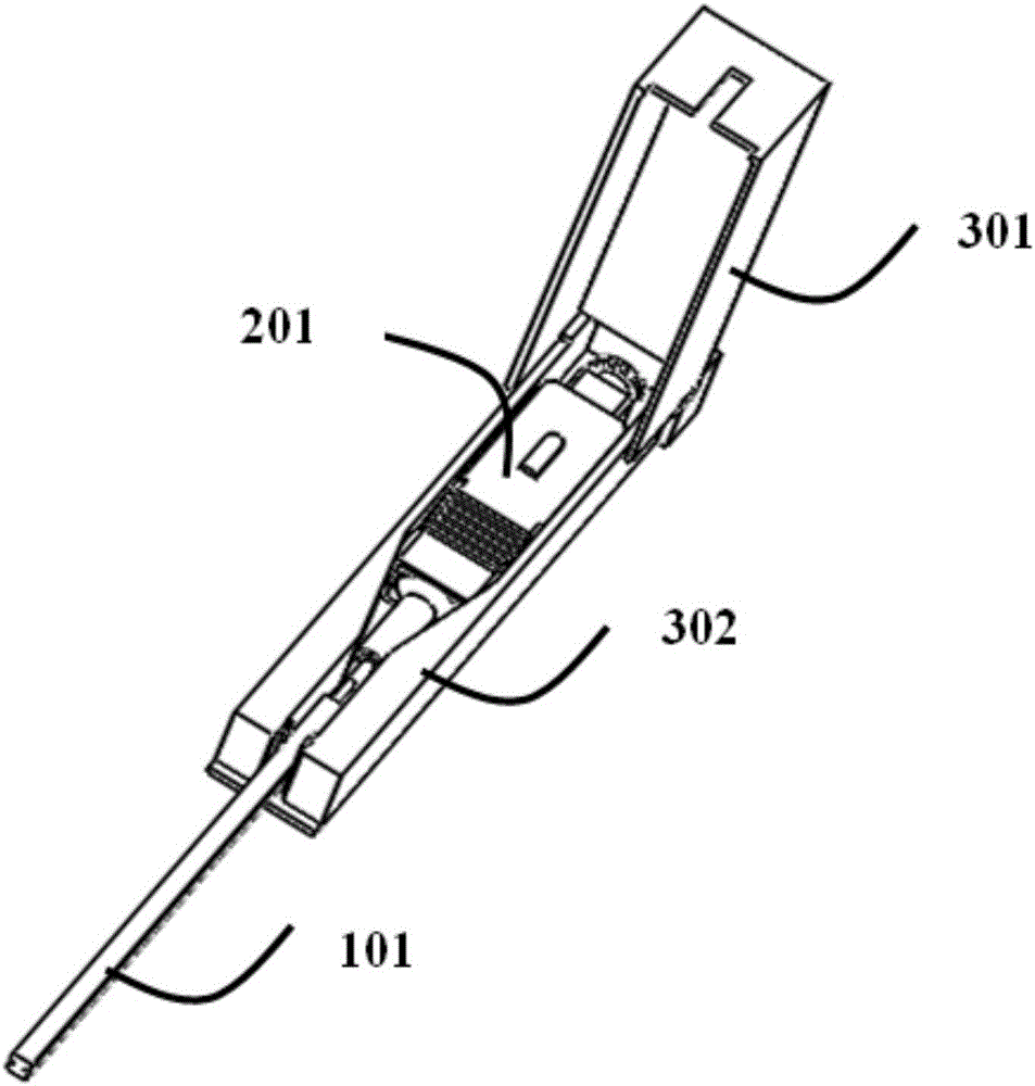
[0048] like Figure 1 to Figure 7 As shown, it is a prefabricated bow-shaped drop cable according to the present invention, which includes a bow-shaped drop cable 101, an optical fiber active connector 201 located at the front end of the butterfly-shaped drop cable 101, and a fiber optic connector 201 for connecting the butterfly cable. The protective groove device of the line and optical fiber active connector 201.
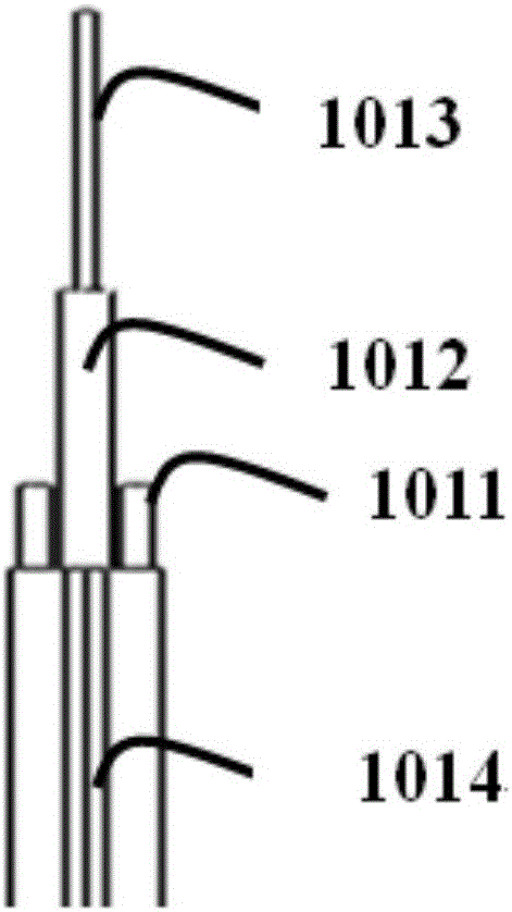
[0049] Wherein the butterfly-shaped lead-in optical cable 101 includes an optical fiber 1013, an outer sheath 1014, a strength member 1011 and a microcable unit 1012, the microcable unit 1012 is arranged on the outer layer of the optical fiber 1013, and the outer sheath 1014 wraps On the outer ring surface of the microcable unit 1012, the strengthening member 1011 is disposed parallel to both sides of the microcable unit 1012, and the strengthening member 1011 ensures the overall strength of the entire optical fiber cable.
[0050] The optical fiber active conne...
Embodiment 2
[0058] A preparation method based on the prefabricated end butterfly drop cable described in embodiment 1, comprising the steps of:
[0059] S1: Stripping the outer sheath 1014 of the prefabricated-end butterfly-shaped lead-in optical cable with a fiber stripping or cable stripping tool;
[0060] S2: thread the tail sleeve 2011, the stopper 2012, and the spring 2013 of the optical fiber active connector 201 into the microcable unit 1012 in sequence;
[0061] S3: Fixing the length of the microcable unit 1012 according to the length used;
[0062] S4: Clean and pre-treat the end face of the optical fiber with a clean alcohol cloth and an optical fiber cutter;
[0063] S5: inserting the ceramic ferrule 2014 with glue, and placing it in a curing furnace for curing, wherein the ceramic ferrule 2014 has a tailstock;
[0064] S6: Assemble white inner core 2015 and SC outer shell 2016;
[0065] S7: After the assembly is completed, the end face of the optical fiber is polished;
[...
Embodiment 3
[0071] A wiring method based on the prefabricated end butterfly lead-in optical cable described in embodiment 1, comprising the following steps:
[0072] E01: Install the optical fiber active connector 201 into the protective groove device to avoid bending and damage to the micro cable unit 1012 during wiring;
[0073] E02: After delivering the optical fiber active connector 201 to the designated area, take the optical fiber active connector 201 out of the protective slot, and strip the outer sheath 1014 of the butterfly-shaped lead-in optical cable 101 to the required length, and remove the stripped outer sheath. The sheath 1014 is cut;
[0074] E03: The stripped 900um micro-cable unit 1012 is coated with a hot-melt glue gun along the wiring route (as far as possible along the corner of the wall), and embedded in the fine groove of the ceiling or wall;
[0075] E04: Insert the optical fiber active connector 201 into the device, fix the butterfly-shaped lead-in optical cable ...
PUM
| Property | Measurement | Unit |
|---|---|---|
| Diameter | aaaaa | aaaaa |
Abstract
Description
Claims
Application Information
 - R&D Engineer
- R&D Manager
- IP Professional
- Industry Leading Data Capabilities
- Powerful AI technology
- Patent DNA Extraction
Browse by: Latest US Patents, China's latest patents, Technical Efficacy Thesaurus, Application Domain, Technology Topic, Popular Technical Reports.
© 2024 PatSnap. All rights reserved.Legal|Privacy policy|Modern Slavery Act Transparency Statement|Sitemap|About US| Contact US: help@patsnap.com


