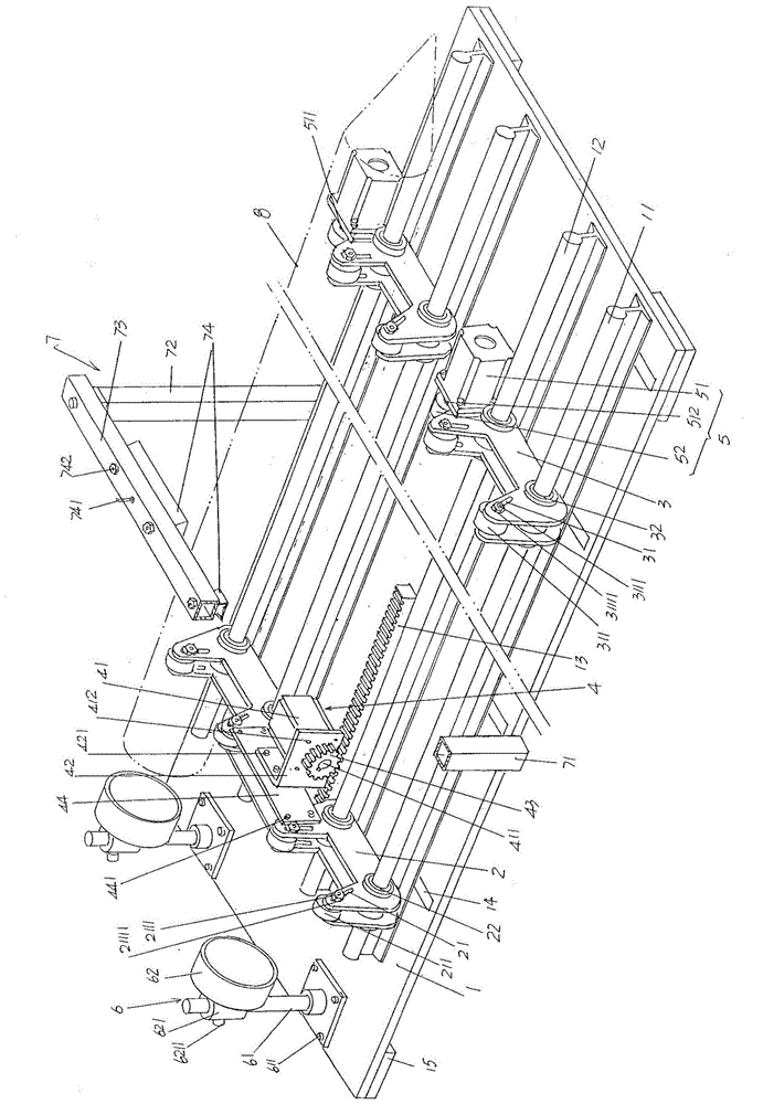
Optical fiber perform rod inspection platform structure

A technology of optical fiber preform and platform structure, which is applied in the direction of using optical devices, optical testing defects/defects, and measuring devices, which can solve the problems of poor adaptability to changes in the diameter of optical fiber preforms, complex overall structure, and high cost, and achieve good economical and cheap Effect, the overall structure is simple, the effect of high equipment utilization

Inactive Publication Date: 2015-11-25
QINGHAI ZHONGLI OPTICAL FIBER TECH CO LTD
View PDF9 Cites 11 Cited by
  • Summary
  • Abstract
  • Description
  • Claims
  • Application Information

AI Technical Summary

Problems solved by technology

The applicant believes that the patented solution can objectively reflect the technical effects of the four aspects summarized in paragraph 0018 of its description, but there are the following shortcomings: First, because the patented solution is aimed at the curvature of the preform (the patent is called eccentricity) Therefore, the inspection items are relatively single; secondly, because the patent fixes the left and right fixed roller brackets (that is, the left and right supporting roller brackets, the same below) to the left and right ends of the mobile slide table respectively, Therefore, the distance between the two is constant, so when inspecting different batches of optical fiber preforms whose length has changed, especially shortened lengths, it is difficult to place the optical fiber preforms on the left and right sides. on roller bracket
Perhaps this patent scheme foresees this factor and is provided with a moving bracket that is equipped with a motor and can be displaced between the left and right fixed roller brackets by manual operation between the left and right fixed roller brackets, but the moving bracket The addition of the frame will make the structure complicated, increase the difficulty of manufacture and lose economy; third, due to the distance between a pair of left support rollers arranged on the left fixed roller bracket and the distance between the pair of left support rollers arranged on the right fixed roller bracket The distance between a pair of right support rollers cannot be changed, so it can only support the optical fiber preform with the same diameter. In the actual production process, the diameter of the optical fiber preform also changes with the batch change. Different, so there is pickiness to the diameter of the optical fiber preform to be inspected, that is, the adaptability to the change of the diameter of the optical fiber preform is poor; Fourth, due to the need to be equipped with the aforementioned mobile slide table in the form of a mobile trolley, the overall structure is complicated and the cost is low. high

Method used


Image

  • Optical fiber perform rod inspection platform structure

Examples


Embodiment Construction

[0020] In order to enable the examiners of the patent office, especially the public, to understand the technical essence and beneficial effects of the present invention more clearly, the applicant will describe in detail the following in the form of examples, but none of the descriptions to the examples is an explanation of the solutions of the present invention. Any equivalent transformation made according to the concept of the present invention which is merely formal but not substantive shall be regarded as the scope of the technical solution of the present invention.

[0021] In the following descriptions, all concepts involving up, down, left, right, front and rear directionality (or orientation) are for the position state of the picture being described, and the purpose is to facilitate the public Therefore, it cannot be understood as a special limitation on the technical solution provided by the present invention.

[0022] See figure 1 , a table top 1 that is preferably a ...


PUM


Abstract

The invention discloses an optical fiber perform rod inspection platform structure, and belongs to the technical field of auxiliary facilities in production of optical fiber preform rods. The inspection platform structure includes a table top plate, one side of the table top plate is fixedly provided with at least one front guide rail and at least one rear guide rail, and one upward side of the left end of the table top plate is fixedly provided with a rack; the inspection platform structure includes at least one left supporting roller bracket cooperating with the front guide rails and the rear guide rails, at least one right supporting roller bracket cooperating with the front guide rails and the rear guide rails, a roller bracket drive mechanism connected with the left supporting roller brackets and engaged with the rack, at least one optical fiber preform rod overturning drive mechanism arranged on the right supporting roller brackets, at least one axial light source mechanism fixed at the left end of the table top plate, and an optical fiber perform rod curvature inspection mechanism fixed on the table top plate. The inspection platform structure has the advantages of more inspection items and high device utilization rate, can adapt to supporting of different-length optical fiber perform rods, can satisfy supporting requirements for optical fiber preform rods with insufficient diameter, and is simple in structure, economic and cheap.

Description

technical field [0001] The invention belongs to the technical field of auxiliary facilities in the production of optical fiber preformed rods, and in particular relates to an inspection platform structure for optical fiber preformed rods. Background technique [0002] The aforementioned optical fiber preform is the raw material for manufacturing quartz series optical fibers, more precisely, it is a prefabricated rod for drawing optical fibers (that is, optical fibers). heavier. In order to ensure the quality of optical fiber preforms, manufacturers of optical fiber preforms and even optical fiber manufacturers usually need to inspect the optical fiber preforms such as linearity, air bubbles and gas lines, and whether there are scratches on the surface. [0003] In the past, the inspection of the aforementioned inspection items is usually carried out by the inspector in the state of manually rotating the optical fiber preform, so as to meet the requirement of comprehensive o...

Claims


Application Information

Patent Timeline
Patent Type & Authority Applications(China)
IPC IPC(8): G01N21/88G01B11/24
Inventor 赵海林袁积鸿王翔刘发燕盛小萍
Owner QINGHAI ZHONGLI OPTICAL FIBER TECH CO LTD
Why Eureka
Try Eureka