Optical nonlinearity measuring device and measuring method for nonlinearity thick photonics materials

A photonic material and optical nonlinear technology, which is applied in the field of optical nonlinear measurement devices, can solve problems such as large errors in optical nonlinear measurement results and incomplete responses of photodetectors, and achieve the effect of improving accuracy

Inactive Publication Date: 2015-11-25
LASER FUSION RES CENT CHINA ACAD OF ENG PHYSICS
View PDF5 Cites 18 Cited by
  • Summary
  • Abstract
  • Description
  • Claims
  • Application Information

AI Technical Summary

Problems solved by technology

However, since the laser emits laser light for optical nonlinear measurement, the laser energy emitted by the laser may be different at different times, and the responses of the two photodetectors are not completely consistent, so the light intensity of the laser emitted by the laser , The difference in energy will also affect the optical nonlinear measurement results of the samples to be tested, and eventually lead to large errors in the optical nonlinear measurement results of the samples to be tested

Method used


Image

  • Optical nonlinearity measuring device and measuring method for nonlinearity thick photonics materials

Examples


Embodiment 1

[0025] An optical nonlinear measuring device for nonlinear thick photonic materials, the optical nonlinear measuring device is mainly used to measure the optical nonlinear parameters of nonlinear optical materials with a thickness exceeding a certain range of Rayleigh length, of course it can also be It is used to measure the optical nonlinear parameters of nonlinear optical materials with thickness less than a certain range of Rayleigh length.

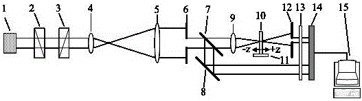
[0026] The optical nonlinear measurement device includes an incident optical path, a measuring optical path, a monitoring optical path, an attenuator 13 , a CCD detector 14 and a computer 15 . The incident optical path includes an adjustable energy laser 1, a half-wave plate 2, a polarizer 3, a lens I4, a lens II5, a pinhole I6 and a beam splitter 7 arranged in sequence, wherein the incident laser light generated by the adjustable energy laser 1 The energy of the laser is adjustable, and the combination of the adjustable energy laser ...

Embodiment 2

[0029] Based on the first embodiment, the transmittance and reflectance of the beam splitter 7 are both 50%. The transmittance and reflectivity of the beam splitter 7 are both 50%, ensuring that the energy of the monitoring light is the same as the energy of the measuring light incident on the sample. Therefore, the monitored light energy can be directly treated as the measured light energy incident on the sample, and the measured light energy obtained by the CCD detector 14 is divided by the monitored light energy to obtain the normalized transmittance of the sample.

Embodiment 3

[0031] On the basis of Embodiment 1 or Embodiment 2, the measuring light in the measuring light path and the monitoring light reflected by the reflector 8 in the monitoring light path are parallel to each other, so that the detecting light is vertically incident on the CCD detector 14, ensuring the energy of the monitoring light The accuracy of the measurement also ensures the compactness and smoothness of the optical path.


PUM

PropertyMeasurementUnit
reflectanceaaaaaaaaaa

Abstract

The invention discloses an optical nonlinearity measuring device and a measuring method for nonlinearity thick photonics materials, and belongs to the technical field of nonlinearity photonics materials and nonlinearity photonics measurement. Tophat type laser pulses serve as probe light, a reference standard sample with the suitable thickness is selected according to the thickness of a sample to be measured, the reference standard sample and the sample to be measured are subjected to Z scanning measurement respectively, energy of incident light is adjusted to obtain the same normalization transmittance peak-to-valley values, and a nonlinearity refraction coefficient of the sample to be measured is obtained by data processing. The optical nonlinearity measuring device and the measuring method for nonlinearity thick photonics materials are suitable for nonlinearity photonics materials of which the thicknesses exceed a Rayleigh length.

Description

technical field [0001] The invention belongs to the technical field of nonlinear photonics materials and nonlinear optical measurement, and relates to an optical nonlinear measurement device and a measurement method for nonlinear photonics materials, in particular to a nonlinear photonics material whose thickness exceeds the Rayleigh length Optical nonlinear measuring device and measuring method. Background technique [0002] In recent years, with the rapid development of high-power laser technology, optical communication and optical information processing and other fields, nonlinear optical materials are widely used in optical switches, all-optical devices, high-speed optoelectronic devices, high-power laser devices, laser protection and optical limiting, etc. The application in this aspect has attracted people's attention day by day. The development of nonlinear optical materials mainly depends on the research of optical nonlinear measurement technology. At present, the ...

Claims


Application Information

Patent Timeline
Patent Type & Authority Applications(China)
IPC IPC(8): G01N21/17G01N21/41G01N21/01
Inventor 张霖任寰杨一马骅陈波石振东李东刘勇原泉杨晓瑜柴立群刘旭巴荣生郑垠波周信达
Owner LASER FUSION RES CENT CHINA ACAD OF ENG PHYSICS
Why Eureka
Try Eureka