
A New Semi-automatic Thread Gauge Comprehensive Measuring Instrument

A technology of comprehensive measuring instrument and thread gauge, which is applied in the field of new semi-automatic thread gauge comprehensive measuring instrument, can solve the problems such as the inability to meet the needs of thread gauge detection, the inability to give a single index, the complex structure of the instrument, etc. Simple and simple device structure

Active Publication Date: 2018-06-19
HARBIN FU RUIDA AIRLINE MACHINERY CO LTD
View PDF9 Cites 0 Cited by
  • Summary
  • Abstract
  • Description
  • Claims
  • Application Information

AI Technical Summary

Problems solved by technology

[0002] At present, the automatic comprehensive measurement of thread gauge is only produced by a very small number of enterprises at home and abroad. This product uses two high-precision gratings as the reference of the two coordinate axes, and uses contact measurement to achieve measurement. The structure of the instrument is complex. , the price is expensive, only a few large-scale thread manufacturing enterprises buy it, and the vast majority of small and medium-sized enterprises cannot afford it, so they can only use the traditional "three-needle method" to detect the pitch diameter of the thread plug gauge, and use the optical method to detect the tooth shape angle, and the thread ring gauge, currently only the proofreading gauge can be used as the acceptance standard, and only comprehensive testing can be performed, and individual indicators cannot be given, and the accuracy is low, which often leads to disputes between the supply and demand sides. With the improvement of customer quality awareness, single piece The demand for small-batch thread product testing is increasing, which leads customers to order more varieties of thread gauge products, less quantity of the same specification, and sometimes even order one or two pairs. In this way, they need to provide proofreading gauges at the same time as they order products, which not only increases The user's cost and a large waste of resources are not conducive to the new concept of energy saving and emission reduction, and green manufacturing; and the profiler products currently available on the market cannot meet the needs of thread gauge detection due to their accuracy and application field positioning.

Method used


Image

  • A New Semi-automatic Thread Gauge Comprehensive Measuring Instrument
  • A New Semi-automatic Thread Gauge Comprehensive Measuring Instrument
  • A New Semi-automatic Thread Gauge Comprehensive Measuring Instrument

Examples


Embodiment 1

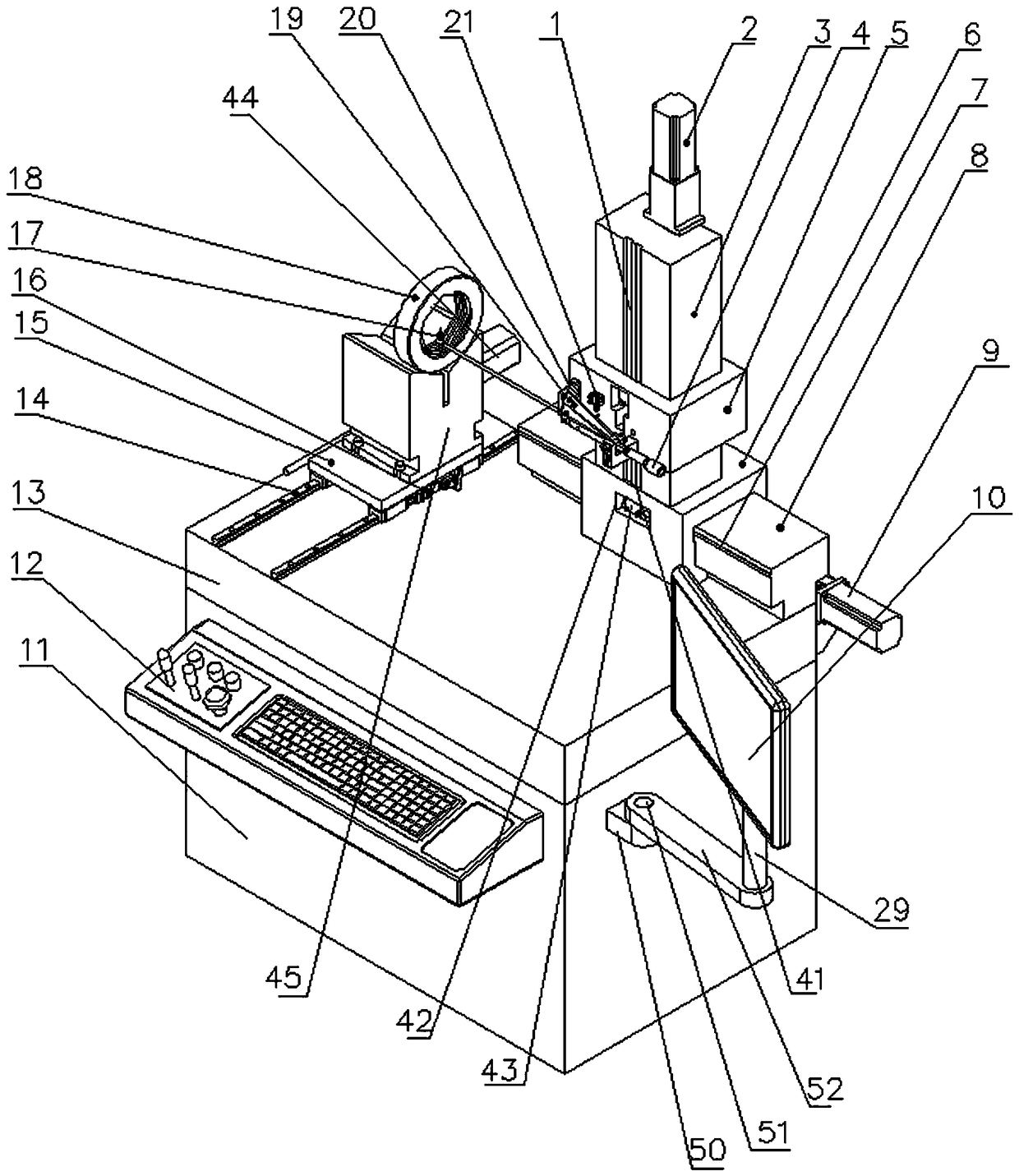
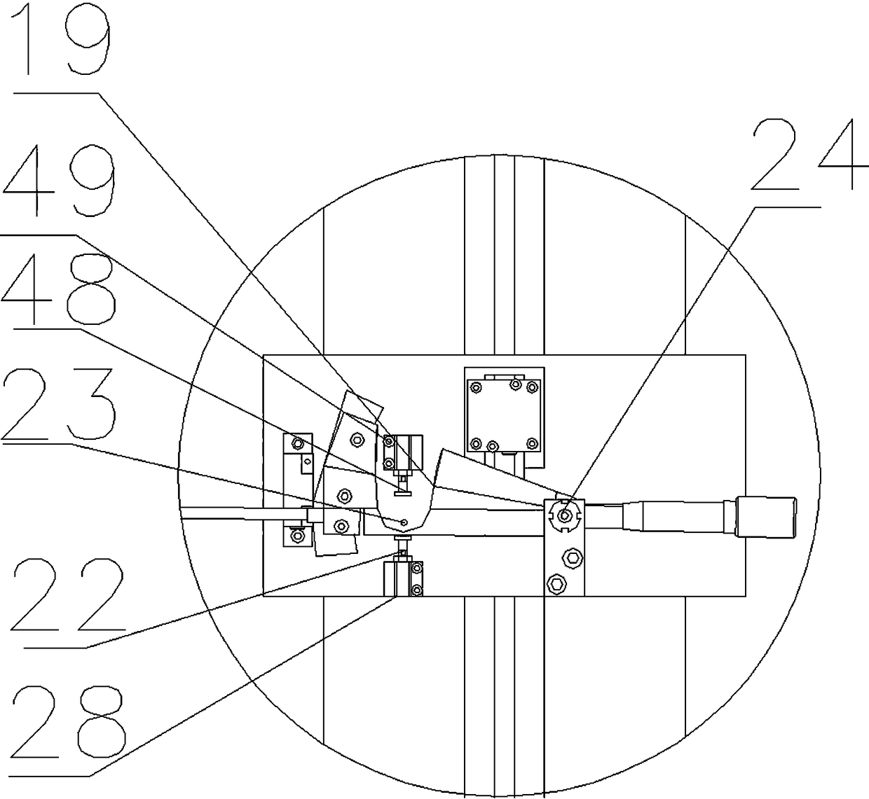
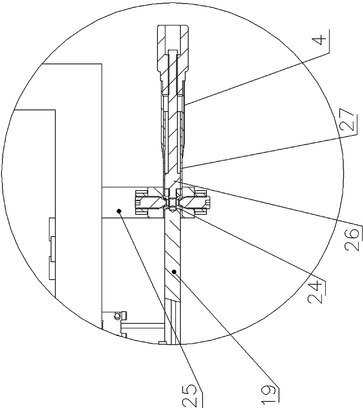
[0029] A new type of semi-automatic thread gauge comprehensive measuring instrument, which consists of: a marble workbench 13, the rear end of the top surface of the marble workbench 13 is connected to the longitudinal air-floating guide rail support column 8, and the longitudinal air-float guide rail support column 8 The rear end is connected to the longitudinal driving servo motor module 9, the front end and the rear end of the longitudinal air-floating guide rail support column 8 are both connected to the longitudinal grating 7, and the longitudinal air-floating guide rail support column 8 is sleeved with the longitudinal carriage 6, The vertical carriage 6 is connected to the column 3, the top surface of the column 3 is connected to the vertical drive servo motor module 2, the front center line of the column 3 is connected to the column grating 1, and the top of the vertical carriage 6 is There is a longitudinal carriage groove 41, and the vertical carriage grating 1 is ins...

Embodiment 2

[0031]In the new semi-automatic thread gauge comprehensive measuring instrument described in Embodiment 1, the left side of the marble workbench 13 is connected with a lateral rolling guide rail 14, and the lateral sliding table 15 slides on the lateral rolling guide rail 14, and the lateral sliding table 15 15 is connected to the lateral drive servo motor module 44, and the bottom end of the lateral sliding table 15 is connected to the lateral locking module 16, and the lateral locking module 16 is used in conjunction with the lateral rolling guide rail 14, and the lateral sliding table 15 is connected with a Y-shaped connection platform 45 with screws, and the top end of the Y-shaped connection platform 45 is connected with the measured thread ring gauge 18.

Embodiment 3

[0033] In the new semi-automatic thread gauge comprehensive measuring instrument described in embodiment 1 or 2, the bottom end of the marble workbench 13 is connected to the base 11, the front of the base 11 is connected to the operation panel 12, and the side of the base 11 passes through The truck is connected to a computer monitor 10 .


PUM


Abstract

A new semi-automatic thread gauge comprehensive measuring instrument. The invention relates to a novel semi-automatic thread gauge comprehensive measuring instrument. The front and rear ends of the longitudinal air-floating guide rail support column 8 are both connected to the longitudinal grating 7, the longitudinal air-floating guide rail support column 8 is sleeved with a longitudinal carriage 6, and the vertical carriage 6 is connected to the column 3 , the top surface of the column 3 is connected to the vertical drive servo motor module 2, the front center line of the column 3 is connected to the column grating 1, and the top of the longitudinal carriage 6 is provided with a longitudinal carriage groove 41. The vertical carriage groove 41 of the vertical carriage groove 41 is loaded with the described column grating 1, and the front surface of the longitudinal carriage groove 41 has a longitudinal carriage opening 42, and the bottom surface of the vertical carriage 3 is connected with the horizontal slider, so The above-mentioned horizontal slider is used with the above-mentioned vertical grating 7, and the vertical carriage 5 is sleeved on the above-mentioned column 3, and the vertical carriage 5 is connected with a sliding shaft 43, and the above-mentioned sliding shaft 43 cooperates with the above-mentioned The column grating 1 is used, and the front surface of the vertical carriage 5 is connected to the measurement module. The invention is used for the comprehensive measurement of thread gauges.

Description

technical field [0001] The invention relates to a novel semi-automatic thread gauge comprehensive measuring instrument. Background technique [0002] At present, the automatic comprehensive measurement of thread gauge is only produced by a very small number of enterprises at home and abroad. This product uses two high-precision gratings as the reference of the two coordinate axes, and uses contact measurement to achieve measurement. The structure of the instrument is complex. , the price is expensive, only a few large-scale thread manufacturing enterprises buy it, and the vast majority of small and medium-sized enterprises cannot afford it, so they can only use the traditional "three-needle method" to detect the pitch diameter of the thread plug gauge, and use the optical method to detect the tooth shape angle, and the thread ring gauge, currently only the proofreading gauge can be used as the acceptance standard, and only comprehensive testing can be performed, and individu...

Claims


Application Information

Patent Timeline
Patent Type & Authority Patents(China)
IPC IPC(8): G01B3/36G01B3/48
Inventor 陶莉李兵张晓红
Owner HARBIN FU RUIDA AIRLINE MACHINERY CO LTD
Learn More