False twisting device for open-end spinning device

A technology of open-end spinning and false twisting, which is used in spinning machines, open-end spinning machines, and continuously wound spinning machines to achieve the effect of improving spinning stability.

Active Publication Date: 2019-08-23
MASCHINENFABRIK RIETER AG
View PDF9 Cites 0 Cited by
  • Summary
  • Abstract
  • Description
  • Claims
  • Application Information

AI Technical Summary

Problems solved by technology

In addition, however, the introduction of false twist is still influenced by the sharpness of the false twist edges, so that the possibility of lossless introduction of false twist is still limited here.

Method used


Image

  • False twisting device for open-end spinning device
  • False twisting device for open-end spinning device
  • False twisting device for open-end spinning device

Examples


Embodiment Construction

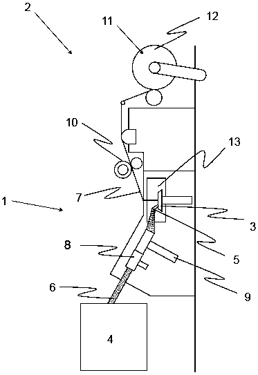
[0032] figure 1A schematic side view of the rotor spinning device 1 of the rotor spinning machine 2 is shown. In this case, the rotor spinning machine 2 comprises a plurality of working points arranged side by side in the longitudinal direction of the spinning machine 2 . Each working point here generally comprises a feed device 8 which feeds the fiber material 6 to the air spinning device 1 via a loosening device 9 which loosens the fiber material 6 into individual fibers. In this case, the fiber material 6 is stored in a storage container 4 on the rotor spinning machine 2 . The fibrous material 6 that is loosened into individual fibers finally passes through the fiber feed channel 5 (see figure 2 ) is delivered to the spinning rotor 3 of the air spinning device 1. The yarn 7 produced in the spinning rotor 3 is finally withdrawn from the open-end spinning device 1 by means of a withdrawal device 10 and wound onto a bobbin 12 by means of a winding device 11 .

[0033] Air...


PUM


Abstract

A false twist device for an open-end spinning device to introduce a false twist in a yarn has a largely tubular carcass and several false twist edges arranged behind one another in the yarn draw-off direction and inclined by an angle in the carcass with regard to the yarn draw-off direction. The false twist edges protrude in such a way into the interior of the tubular carcass that the yarn experiences a deflection on each one of the false twist edges. The several false twist edges are arranged offset in such a way in the carcass in circumferential direction that the yarn simultaneously experiences a spatial deflection compared to its regular yarn draw-off direction through the successive deflections on the several false twist edges.

Description

technical field [0001] The invention relates to a false twist device for an air spinning device for introducing false twist into a yarn produced by the air spinning device. The false twist device has a substantially cylindrical body and a plurality of false twist edges arranged in the main body one behind the other in the thread withdrawal direction and at an angle relative to the thread withdrawal direction. Furthermore, the invention relates to an air-spun spinning device having such a false-twisting device and a method for introducing false-twisting into a yarn produced in an air-spun spinning device of a rotor spinning machine. Background technique [0002] When the yarn is produced in the air-spinning spinning device of the rotor spinning machine, the spun fibers loosened into single fibers are conveyed to the spinning device, and are used as a pre-spinning process by means of a drawing nozzle centrally arranged in the spinning device. The twisted yarn is drawn out. H...

Claims


Application Information

Patent Timeline
Patent Type & Authority Patents(China)
IPC IPC(8): D01H4/02
CPCD01H4/40D01H7/90
Inventor G·斯塔莱克S·克罗默尔G·鲍尔M·巴斯廷
Owner MASCHINENFABRIK RIETER AG
Why Eureka
Try Eureka