Automation device and method for reducing jitter

An automatic device and time technology, applied in the direction of synchronization device, multi-programming device, general control system, etc., can solve problems such as interruption of operation and interference

Active Publication Date: 2015-11-18
PHOENIX CONTACT GMBH & CO KG
View PDF7 Cites 2 Cited by
  • Summary
  • Abstract
  • Description
  • Claims
  • Application Information

AI Technical Summary

Problems solved by technology

Then these interrupt operations may interfere with each other

Method used


Image

  • Automation device and method for reducing jitter
  • Automation device and method for reducing jitter
  • Automation device and method for reducing jitter

Examples


Embodiment Construction

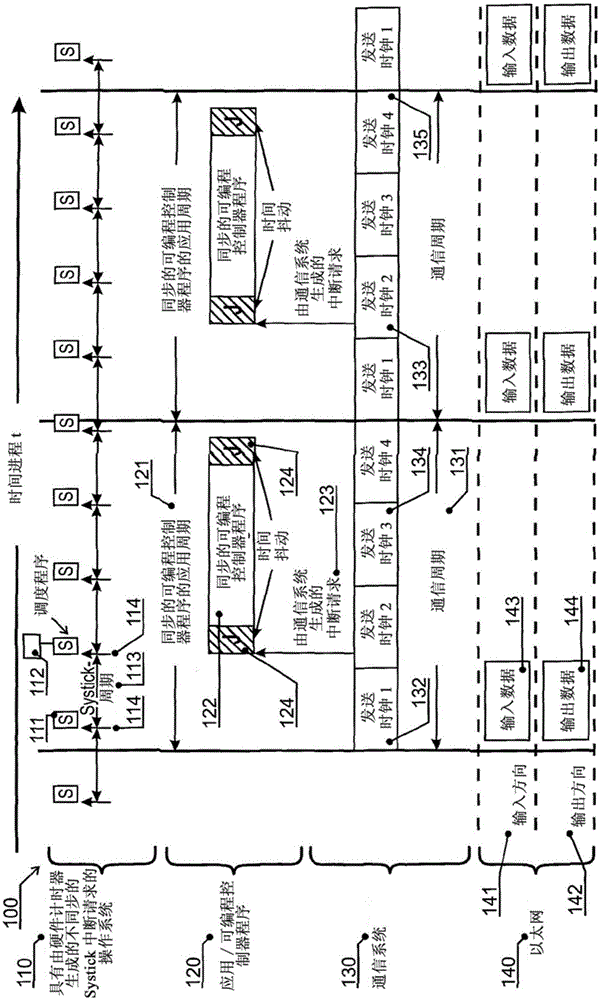
[0015] figure 1 An exemplary embodiment of an automation system according to the prior art with an asynchronous operating system clock is shown. exist figure 1 The automation device 100 shown in has different communication levels. The highest level forms the operating system 110 . In the layer below it, ie in the application layer 120 , an application 122 is executed. Below the application layer 120 is a communication system 130 , below which is an Ethernet bus 140 with an input direction 141 and an output direction 142 , wherein input data 143 are transmitted in the input direction 141 and outputs are transmitted in the output direction 142 Data 144.

[0016] exist figure 1 As can be seen in , asynchronous work between the communication system 130 and the operating system 110 is common in the current state of the art. A system clock of the operating system 110 and corresponding system interrupts are generated in part of the operating system 110 by means of a scheduler 1...


PUM


Abstract

The invention relates to an automation device (200), which has an operating system (210) having a first system clock pulse and a communication system (230) having a second system clock pulse. The first system clock pulse is intended to control a system time cycle (213) of the operating system (210), and the second system clock pulse is intended to control a system time cycle (231) of the communication system (230). Furthermore, the first system clock pulse and the second system clock pulse are synchronized.

Description

technical field Background technique [0001] In automation technology, it is worth noting that the demand for control technology such as SPS (Speicher-Programmierbare-Steuerung, Programmable Logic Controller) is constantly increasing. Shorter and shorter cycle times are required both for SPS programs and for real-time communication systems for the transfer of process data to fieldbus devices. Even Ethernet-based systems are used instead of the hitherto used fieldbus systems, for example of the Interbus or Profibus type. [0002] An automation device has several communication layers, for example a data bus as one layer, a communication system as the next higher layer, an application layer above it and an operating system as the highest layer. In current communication systems it is often provided that a plurality of communication subscribers are synchronized. Such a type of communication is known, for example, from document EP2110754A1. It proposes a method for synchronizing...

Claims


Application Information

Patent Timeline
Patent Type & Authority Applications(China)
IPC IPC(8): H04J3/06H04L12/40
CPCG05B19/05G05B19/00G06F1/14G06F13/00H04J3/0635H04L12/40013H04W56/001G06F16/178H04L67/1095G06F9/52H04L67/1097G06F9/4812G05B2219/1211G06F1/12G01F1/12
Inventor 福尔克尔·德特尔特克里斯托夫·罗特
Owner PHOENIX CONTACT GMBH & CO KG
Why Eureka
Try Eureka