Optical film and method for fabrication of same, and polarizing plate, liquid-crystal display device, and polarizing projector screen provided with optical film
An optical film, optical technology, applied in the direction of optics, optical components, optical components, etc., can solve the problem of low utilization efficiency and achieve the effect of easy production
- Summary
- Abstract
- Description
- Claims
- Application Information
AI Technical Summary
Problems solved by technology
Method used
Image

Examples
Embodiment 1
[0118] (1) Synthesis of the first resin forming an optically isotropic continuous phase
[0119] A total of 300 parts by mass of deionized water and 0.6 parts by mass of polyvinyl alcohol (Kuraray Poval manufactured by Kuraray Co., Ltd.) as a dispersant were added to a reactor equipped with a stirring device, a temperature sensor, a cooling pipe, and a nitrogen gas introduction pipe, and stirring was started. Next, 85 parts by mass of methyl methacrylate (MMA), 15 parts by mass of N-cyclohexylmaleimide (CHMI), 1 part by mass of PEROYLTCP from NOF Corporation as a polymerization initiator, and 0.22 parts by mass of 1-octyl mercaptan, nitrogen was blown in and the temperature was raised to 70°C. After holding the state which reached 70 degreeC for 3 hours, it cooled, filtered, wash|cleaned, and dried, and obtained the particulate-form acrylic-type polymer.
[0120] The weight average molecular weight of the obtained acrylic polymer is 1.5×10 5 , the glass transition temperatur...
Embodiment 2
[0137] Except having changed the stretching temperature of the original film of said (5) into 144 degreeC, the optical film was produced by the method similar to Example 1. In addition, when the stretching temperature was changed to 144°C and the evaluation of (2) above was performed, the Re was 6.9 nm and the birefringence was 1.5×10 -4 .
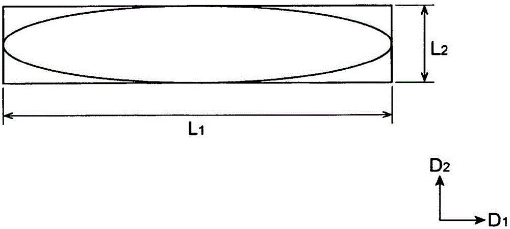
[0138] In addition, in the obtained optical film, the average Feret diameter L of the dispersed phase 1 1.5 μm, average Feret diameter L 2 0.15μm, its ratio: L 1 / L 2 for 10. In addition, the luminance improvement rate measured in the same manner as the above (6) was 9.8%.
[0139] In addition, the obtained optical film was evaluated in the same manner as the image visibility evaluation when used as the polarized light projector screen of Example 1. polarized projector screen.
Embodiment 3
[0141] In the synthesis method of the first resin forming an optically isotropic continuous phase, the composition of the resin is 81 parts by mass of methyl methacrylate (MMA) and 11 parts by mass of N-cyclohexylmaleimide (CHMI). , N-phenylmaleimide (PhMI) 8 mass parts, the optical film was obtained by the method similar to Example 1. The weight average molecular weight of the obtained acrylic polymer is 1.5×10 5 , Tg is 130°C. In addition, the refractive index N of the non-oriented state 1 is 1.502. The obtained original film was uniaxially stretched at the free end in the same direction as the flow direction of the original film using a batch stretcher manufactured by Imoto Seisakusho (extension temperature: Tg of the continuous phase + 9°C (139°C), stretching The in-plane retardation Re in the case of magnification: 1.4 times) was 4.8 nm. That is, the birefringence is a very small 8.0×10 -5 . The reason is that the composition ratio of the copolymer is adjusted so th...
PUM
| Property | Measurement | Unit |
|---|---|---|
| Diameter | aaaaa | aaaaa |
| Thickness | aaaaa | aaaaa |
| Glass transition temperature | aaaaa | aaaaa |
Abstract
Description
Claims
Application Information
 - Generate Ideas
- Intellectual Property
- Life Sciences
- Materials
- Tech Scout
- Unparalleled Data Quality
- Higher Quality Content
- 60% Fewer Hallucinations
Browse by: Latest US Patents, China's latest patents, Technical Efficacy Thesaurus, Application Domain, Technology Topic, Popular Technical Reports.
© 2025 PatSnap. All rights reserved.Legal|Privacy policy|Modern Slavery Act Transparency Statement|Sitemap|About US| Contact US: help@patsnap.com