Hydraulic system for construction equipment

A hydraulic system and engineering machinery technology, applied in the field of hydraulic systems, can solve problems such as low energy efficiency and pressure loss, and achieve the effects of eliminating pressure differences, improving fuel economy, and improving operational controllability

Active Publication Date: 2015-11-18
HYUNDAI DOOSAN INVIGORATE CORP
View PDF5 Cites 3 Cited by
  • Summary
  • Abstract
  • Description
  • Claims
  • Application Information

AI Technical Summary

Problems solved by technology

That is, the pressure of the working oil discharged from the main control valve will inevitably suffer a pressure loss while passing through the main control valve and various valves, and there is a problem of low energy efficiency.

Method used


Image

  • Hydraulic system for construction equipment
  • Hydraulic system for construction equipment
  • Hydraulic system for construction equipment

Examples


Embodiment Construction

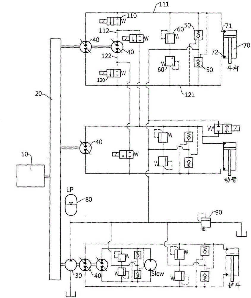
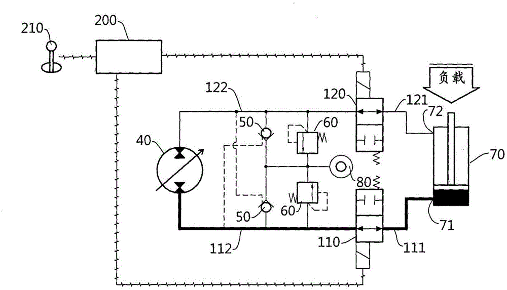
[0029] If referring to the following and attached Figure 1 With the detailed description of the embodiments, the advantages and characteristics of the present invention and the method for achieving them will be clarified.

[0030] Embodiments of the present invention will be described in detail below with reference to the accompanying drawings. The embodiments described below are exemplified to facilitate understanding of the present invention, and it should be understood that the present invention can be variously modified and implemented differently from the embodiments described here. However, in describing the present invention, when it is judged that the specific description of related known functions or components may unnecessarily obscure the gist of the present invention, the detailed description and specific illustrations will be omitted. In addition, the drawings are not shown on an actual scale to facilitate understanding of the invention, and the size of some com...


PUM


Abstract

The present invention relates to a hydraulic system for construction equipment and, more specifically, to a hydraulic system of which an actuator is controlled by a pump / motor. The hydraulic system for construction equipment according to the present invention includes logic valves respectively provided to first and second hydraulic lines provided to the actuator. In addition, when the actuator must be operated in a state in which the operation of the actuator is stopped by the closing of the logic values, a pressure difference can be resolved by increasing the pressure in the pump / motor and logic value sections in advance even if a load is applied to the actuator, and thus the actuator can implement a desired operation without being affected by the load. That is, operation controllability of the actuator can be improved.

Description

technical field [0001] The present invention relates to a hydraulic system of construction machinery, and more specifically, to a hydraulic system in which a driver is controlled by a pump / motor. Background technique [0002] Generally speaking, the hydraulic system of construction machinery includes: an engine, which generates power; a main hydraulic pump, which receives the power of the engine and drives it, and discharges working oil; a plurality of drives, which perform tasks; The driver of the working machine operates; the main control valve distributes the required working oil to the corresponding driver according to the operation of the operating part. [0003] The operation unit forms a request command according to the operation displacement operated by the operator, and controls the flow rate of hydraulic oil discharged from the hydraulic pump according to the request command. The operating unit includes, for example, a joystick, a pedal, and the like. [0004] In...

Claims


Application Information

Patent Timeline
Patent Type & Authority Applications(China)
IPC IPC(8): E02F9/22F15B13/02
CPCE02F9/2296E02F9/2217E02F9/2228E02F9/2289E02F9/2292F15B7/006F15B11/17F15B21/14F15B2211/20523F15B2211/20546F15B2211/20561F15B2211/20569F15B2211/20576F15B2211/27F15B2211/30515F15B2211/3057F15B2211/30595F15B2211/31529F15B2211/327F15B2211/613F15B2211/625F15B2211/6346F15B2211/7142F15B2211/88F15B11/10F15B13/042
Inventor 安敏河郑雨容赵镕乐徐雅凛张达植林光镐
Owner HYUNDAI DOOSAN INVIGORATE CORP
Why Eureka
Try Eureka