
Method and device for generating pulse width modulation signal

A technology of pulse width modulation signal and pulse width modulation, which is applied in the direction of pulse duration/width modulation, etc., and can solve problems such as long response time

Active Publication Date: 2018-07-03
ZOOMLION HEAVY IND CO LTD
View PDF4 Cites 0 Cited by
  • Summary
  • Abstract
  • Description
  • Claims
  • Application Information

AI Technical Summary

Problems solved by technology

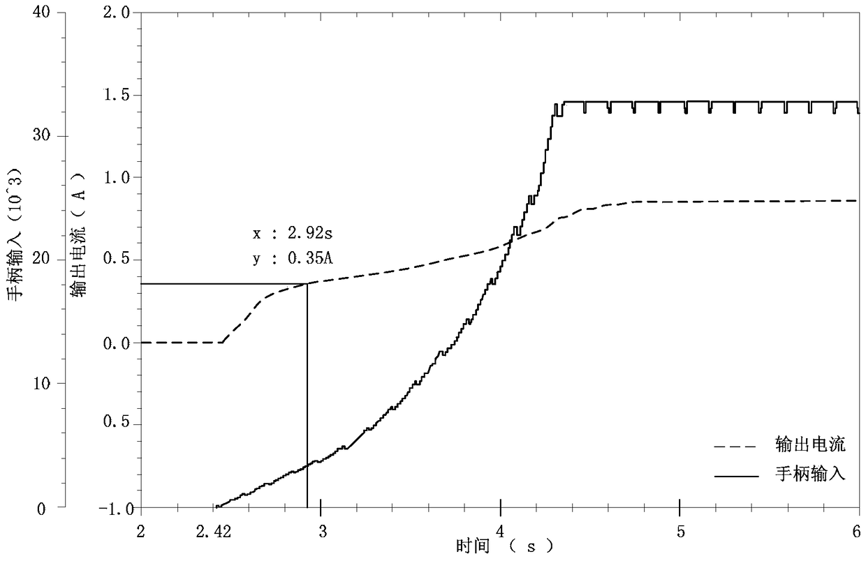
[0012] The embodiment of the present invention provides a method and device for generating a pulse width modulation signal to at least solve the technical problem of long response time to control commands due to the fact that the traditional Motion module starts to accumulate the output current from zero.

Method used


Image

  • Method and device for generating pulse width modulation signal
  • Method and device for generating pulse width modulation signal
  • Method and device for generating pulse width modulation signal

Examples


Embodiment Construction

[0034]In order to enable those skilled in the art to better understand the solutions of the present invention, the following will clearly and completely describe the technical solutions in the embodiments of the present invention in conjunction with the drawings in the embodiments of the present invention. Obviously, the described embodiments are only It is an embodiment of a part of the present invention, but not all embodiments. Based on the embodiments of the present invention, all other embodiments obtained by persons of ordinary skill in the art without making creative efforts shall fall within the protection scope of the present invention.

[0035] It should be noted that the terms "first" and "second" in the description and claims of the present invention and the above drawings are used to distinguish similar objects, but not necessarily used to describe a specific sequence or sequence. It is to be understood that the data so used are interchangeable under appropriate c...


PUM


Abstract

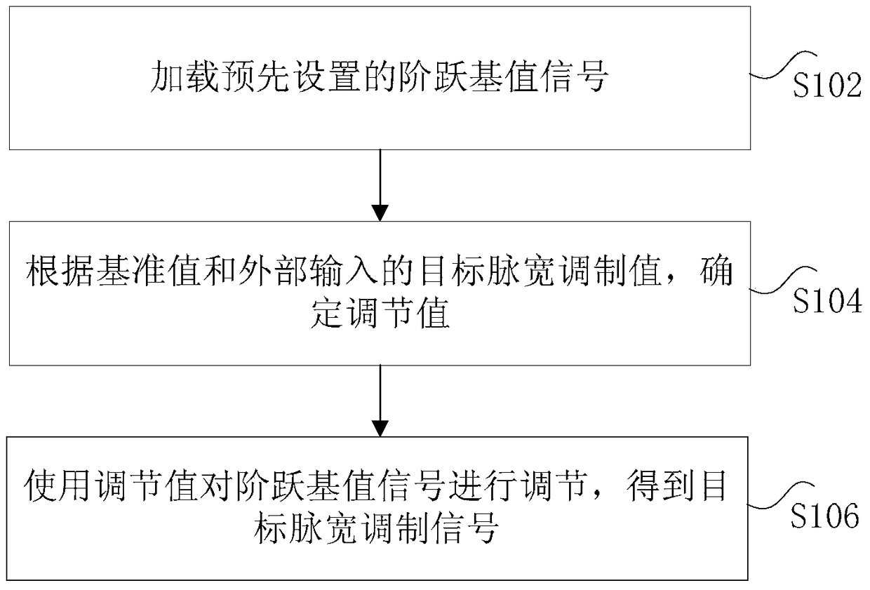
The invention discloses a method and a device for generating a pulse width modulation signal. Wherein, the method includes: loading a preset step base value signal, wherein the step base value signal includes: a reference value obtained by the controller before performing a step response; a target pulse width modulation value according to the reference value and external input , to determine the adjustment value; use the adjustment value to adjust the step base value signal to obtain a target pulse width modulation signal, wherein the target pulse width modulation signal is used to drive the external drive module. The invention solves the technical problem of long response time to and control commands due to the traditional Motion module accumulating the output current from zero.

Description

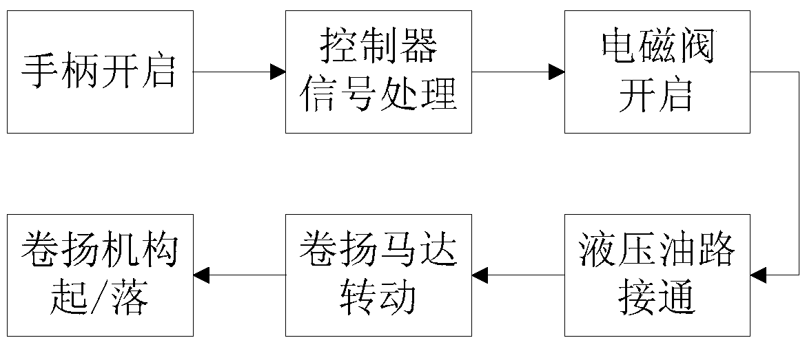
technical field [0001] The invention relates to the field of automatic control, in particular to a method and device for generating a pulse width modulation signal. Background technique [0002] At present, in the field of automatic control, the response speed of the solenoid valve often directly determines the control performance of the control system. The faster the response speed of the solenoid valve, the faster the response of the control system, making the response more timely and precise. [0003] Take the truck crane in construction machinery as an example, such as figure 1 As shown, when the winch handle is pulled, the control command is transmitted to the controller. The controller outputs a control signal corresponding to the control command to the solenoid valve, so that the solenoid valve is opened and the hydraulic oil circuit is connected. The winch motor starts to rotate after being fully supplied with oil, thereby driving the winch mechanism to lift or de...

Claims


Application Information

Patent Timeline
Patent Type & Authority Patents(China)
IPC IPC(8): H03K7/08
Inventor 田炯明郭纪梅毛艳
Owner ZOOMLION HEAVY IND CO LTD
Learn More