
High-impedance transformer coil winding device and method

A technology of high-impedance transformers and winding methods, which is applied in the direction of coil manufacturing, etc., can solve problems such as waveform variation, noise increase, transformer stray loss, etc., and achieve the effects of simple components, cost saving, and improved winding efficiency

Active Publication Date: 2015-11-18
襄阳中车电机技术有限公司 +1
View PDF5 Cites 3 Cited by
  • Summary
  • Abstract
  • Description
  • Claims
  • Application Information

AI Technical Summary

Problems solved by technology

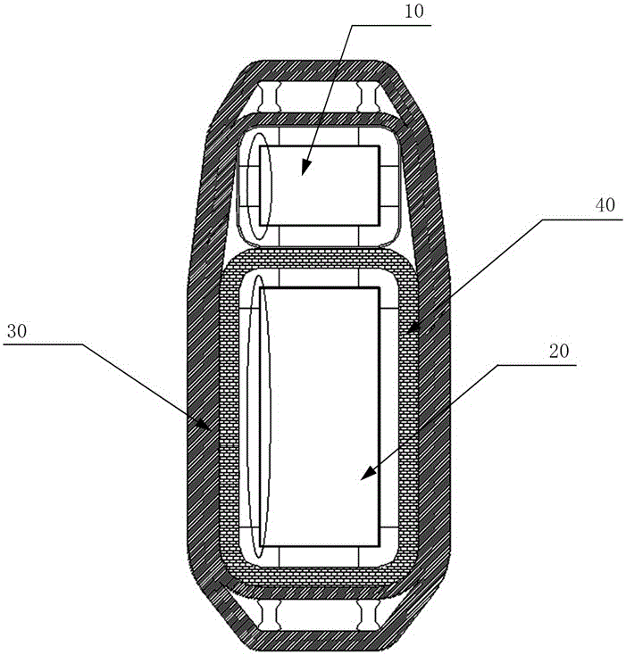
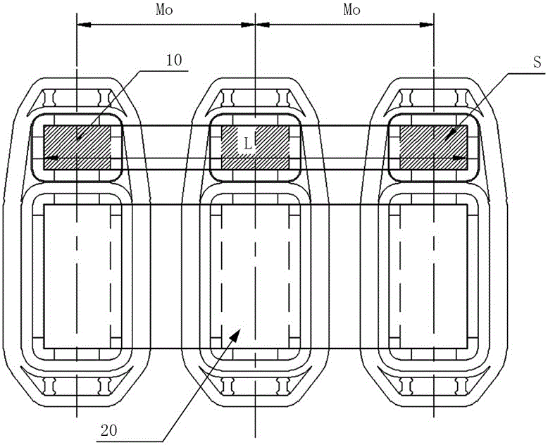
[0007] In view of this, the object of the present invention is to provide a high-impedance transformer coil winding device and method, which can ensure that the secondary iron core pole does not shift when the high-impedance transformer coil is wound, thereby solving the problem caused by the secondary iron core pole offset. Waveform changes, transformer stray loss and technical problems of noise increase

Method used


Image

  • High-impedance transformer coil winding device and method
  • High-impedance transformer coil winding device and method
  • High-impedance transformer coil winding device and method

Examples


specific Embodiment

[0063] A specific embodiment of a high-impedance transformer coil winding method utilizing the above-mentioned device, comprising the following steps:

[0064] S100: Use bolts to fix the two splints 2 on the collet of the winding machine fixing plate 9 through the matching hole 6 of the winding machine fixing plate;

[0065] S101: Adjust the distance between the two splints 2 to be greater than the width of the laminations of the auxiliary iron core column 10 and the main iron core column 20; as a typical embodiment of the present invention, adjust the distance between the two splints 2 to be greater than The width of the laminations of the auxiliary iron core column 10 and the main iron core column 20 is 2 mm;

[0066] S102: Turn the winding machine so that the splint 2 is parallel to the ground, install two first stoppers 3, and make the distance between the two first stoppers 3 greater than the lamination thickness of the main core column 20;

[0067] S103: install the mai...


PUM


Abstract

The invention discloses a high-impedance transformer coil winding device and method which are used for winding coils of a secondary iron core and a main iron core of a high-impedance transformer. The device comprises two clamping plates which are oppositely arranged in parallel, two first stop blocks which are oppositely arranged between the two clamping plates in parallel and a second stop block which is parallel to the first stop block and is arranged between the two clamping plates; the clamping plates serve as a support framework of the coil winding device and are used for limiting the displacement of core columns of the secondary iron core and the main iron core in the width direction of laminations; a space used for fixing the core column of the main iron core is formed between the first stop blocks and used for limiting the displacement of the core column of the main iron core in the thickness direction of the laminations; a space used for fixing the core column of the secondary iron core is formed between one first stop block and the second stop block and used for limiting the displacement of the core column of the secondary iron core in the thickness direction of the laminations. According to the high-impedance transformer coil winding device and method, it can be guaranteed that the offset of the core column of the secondary iron core does not occur when the high-impedance transformer coil is wound, and therefore the technical problems of waveform distortion, transformer stray losses and noise increasing which are caused by the offset of the core column of the secondary iron core are solved.

Description

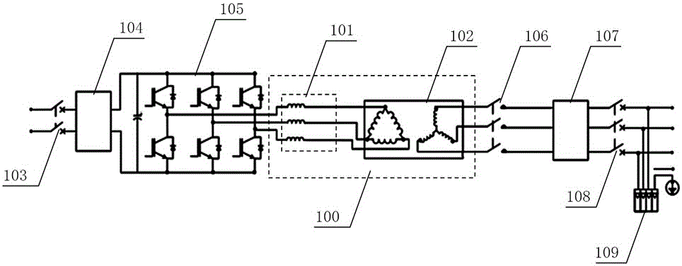
technical field [0001] The invention relates to a coil winding device and method, in particular to a coil winding device and method applied to high impedance transformers. Background technique [0002] High-impedance transformers are mainly used in photovoltaic inverter systems. figure 1 The photovoltaic inverter system shown includes: LC filter 101, three-phase transformer 102, DC circuit breaker 103, DC EMC filter 104, three-phase full-bridge IGBT main power circuit 105, AC main contactor 106, AC EMC filter 107, AC circuit breaker 108 and AC lightning protection device 109. In a typical circuit of a photovoltaic inverter system, the three-phase power output from the three-phase full-bridge IGBT main power circuit 105 is rich in harmonics and cannot be used directly. It needs to pass through an LC filter (a filter composed of a reactor and a capacitor, In the figure, the capacitor) 101 is omitted for filtering, and at the same time, the small and medium power photovoltaic...

Claims


Application Information

Patent Timeline
IPC IPC(8): H01F41/06
Inventor 於军红孙磊徐锦星张木生
Owner 襄阳中车电机技术有限公司
Learn More