
Hardness testing device beneficial to test precision

A technology for testing accuracy and testing instruments, which is applied in the direction of testing material hardness, instruments, and measuring devices. It can solve problems that affect test results, easily generate vibration, and cannot be placed smoothly, and achieve accurate test results.

Active Publication Date: 2015-11-18
API ZC PRECISION INSTUMENT CO LTD
View PDF5 Cites 4 Cited by
  • Summary
  • Abstract
  • Description
  • Claims
  • Application Information

AI Technical Summary

Problems solved by technology

However, when using it to test those cylindrical workpieces with a large aspect ratio, because it cannot be placed on the surface of the base smoothly, it is easy to generate vibration and affect the test results when subjected to slight vibration.

Method used


Image

  • Hardness testing device beneficial to test precision
  • Hardness testing device beneficial to test precision
  • Hardness testing device beneficial to test precision

Examples


Embodiment 1

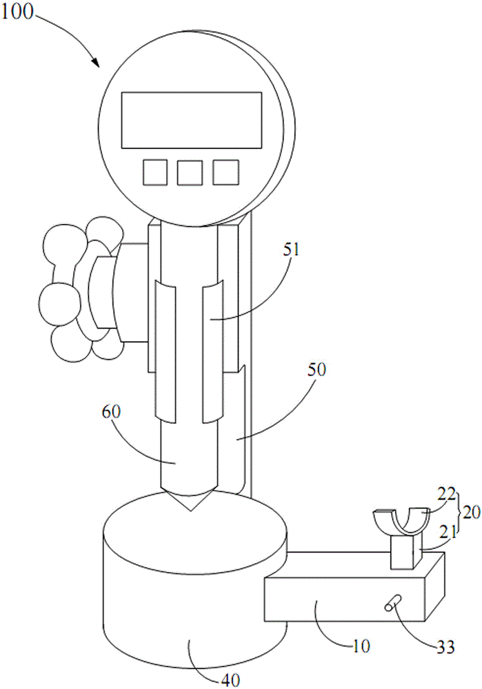
[0017] see Figure 1-3 , the hardness tester 100 shown in the preferred embodiment of the present invention includes a base 40 , a column 50 fixedly connected to the base 40 , a Shore hardness tester 60 and an external insert fixedly connected to the base 40 .

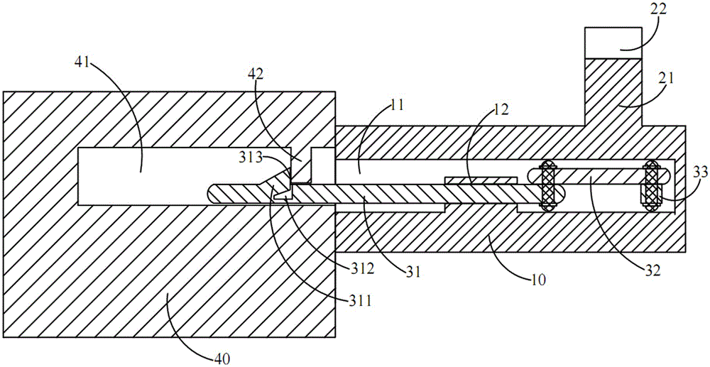
[0018] The base 40 is a cylindrical structure, a fixing hole 41 is opened on the side wall of the base 40, and a locking block 42 protrudes from the side wall of the fixing hole 41, and the locking block 42 is matched with the outer plug , so that the external insert is fixedly connected with the base 40 .

[0019] A clamp 51 for clamping the Shore hardness tester 60 protrudes from one side of the column 50 .

[0020] The external insert includes a base body 10, a fixing piece 20 and a plug-in assembly.

[0021] One end of the base body 10 is adjacent to the side wall of the base 40 . One end of the base body 10 adjacent to the base 40 defines a cavity 11 for matching with the plug-in assembly. A boss 12 with a thr...


PUM


Abstract

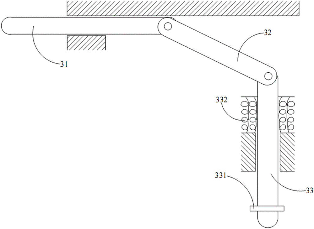
The invention discloses a hardness testing device beneficial to test precision. The hardness testing device comprises a base, a stand column fixedly connected with the base, a shore hardness tester clamped on the stand column, and an external insertion piece fixedly connected with the base. A fixing hole with a clamping block is formed in the side wall of the base. The external insertion piece comprises a base body with a cavity, a fixing piece and an insertion connection assembly. A boss protrudes and extends out of the cavity. The fixing piece comprises a column body fixedly connected with the base body, and an arc-shaped fixing block. The arc-shaped fixing block is used for fixing a columnar workpiece. The insertion connection assembly comprises an insertion rod, a connection rod and a push rod. One end of the connection rod is hinged to the insertion rod, and the other end of the connection rod is hinged to the push rod. The insertion rod penetrates through the boss. A containing groove is formed in the end, away from the connection rod, of the insertion rod. One end of an elastic protruding strip is fixedly connected with the side wall of the containing groove, and the other end of the elastic protruding strip is supported and held by the clamping block. The push rod and the insertion rod are arranged in a perpendicular mode. The push rod can slide relative to the base body. The hardness testing device is suitable for hardness detection of the columnar workpiece.

Description

technical field [0001] The invention relates to the field of hardness detection, in particular to a hardness tester which is beneficial to testing accuracy. Background technique [0002] The Shore hardness test method was proposed by American Shore in 1907. It has the characteristics of rapid testing, shallow and small indentation, and simple operation. It is widely used in metallurgy, heavy machinery, and large-scale, heavy-weight test pieces. Hardness Testing. [0003] The Shore hardness tester can be measured by hand, but because the manual force control is not very stable, it is usually possible to use a stand to improve the measurement accuracy. The stand of the Shore hardness tester usually mainly includes a base and a column for clamping the hardness tester. The surface of the base of the Shore hardness tester stand is a plane. When using it to test some small parts or to place it stably More accurate results can be obtained when using parts on the surface of the ba...

Claims


Application Information

Patent Timeline
IPC IPC(8): G01N3/52G01N3/02
Inventor 刘宁周姝李德维王伟
Owner API ZC PRECISION INSTUMENT CO LTD
Learn More