
Turbine-piston combined cycle engine ejection system

A combined cycle and engine technology, used in engine testing, machine/structural component testing, measuring devices, etc., can solve problems such as difficulty in starting the engine at low speeds, and achieve the effects of easy implementation, wide popularization and application, and simple structure.

Inactive Publication Date: 2015-11-18
CHINA NORTH ENGINE INST TIANJIN
View PDF5 Cites 2 Cited by
  • Summary
  • Abstract
  • Description
  • Claims
  • Application Information

AI Technical Summary

Problems solved by technology

[0004] In view of this, the present invention aims to propose a turbo-piston combined cycle engine injection system to solve the problem that the turbo-piston combined cycle engine is difficult to start at a low speed

Method used


Image

  • Turbine-piston combined cycle engine ejection system
  • Turbine-piston combined cycle engine ejection system

Examples


Embodiment Construction

[0020] It should be noted that, in the case of no conflict, the embodiments of the present invention and the features in the embodiments can be combined with each other.

[0021] The present invention will be described in detail below with reference to the accompanying drawings and examples.

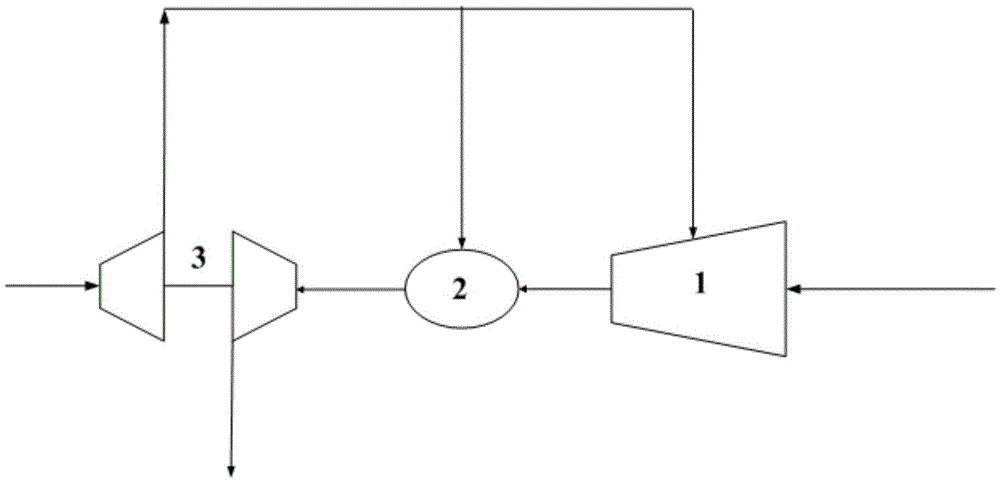
[0022] A turbo-piston combined cycle engine injection system, such as figure 1 As shown, it includes an ejector 1, an auxiliary combustion chamber 2 and a supercharger 3, the front end of the ejector 1 is connected to the compressor outlet of the supercharger 3, and the rear end of the ejector 1 is connected to the front end of the auxiliary combustion chamber 2 , the rear end of the auxiliary combustion chamber 2 is connected to the turbine inlet of the supercharger 3, and the front end of the auxiliary combustion chamber 2 is also connected to the compressor outlet of the supercharger 3.

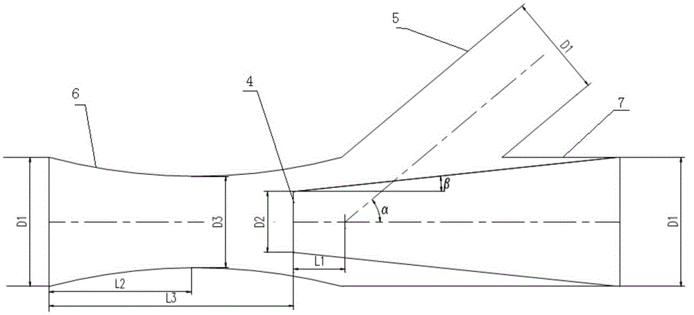
[0023] The ejector of the present invention is mainly made up of nozzle 4, nozzle pipeline 7, in...


PUM


Abstract

The invention provides a turbine-piston combined cycle engine ejection system, which comprises an ejector, an auxiliary combustion chamber and a pressurizer, wherein the front end of the ejector is connected with a gas compressor outlet of the pressurizer, the rear end of the ejector is connected with the front end of the auxiliary combustion chamber, the rear end of the auxiliary combustion chamber is connected with a turbine inlet of the pressurizer, and the front end of the auxiliary combustion chamber is connected with the gas compressor outlet of the pressurizer; and part of the gas at the gas compressor outlet of the pressurizer is guided into the ejector and the auxiliary combustion chamber, so as to form pressure difference between the gas compressor outlet and the turbine inlet gradually. The turbine-piston combined cycle engine ejection system has the advantages of filling in a gap of low-speed starting of a turbine-piston combined cycle engine simulation verification system, satisfying ignition requirement of the auxiliary combustion chamber of the cycle engine and starting requirement of a power turbine, further studying the combined cycle process of a diesel engine and the power turbine, and achieving the test verification of the turbine-piston combined cycle engine.

Description

technical field [0001] The invention belongs to the technical field of engines, in particular to a turbo-piston combined cycle engine injection system. Background technique [0002] With the development of army weapons and equipment in modern warfare, the performance requirements of armored combat vehicle engines are getting higher and higher. It is required that the engine can provide a large amount of super value power when the vehicle-mounted weapon system is working. The turbo-piston combined cycle engine can meet the super-value power requirements of high-energy weapon systems and other vehicle power. [0003] Through the simulation and verification system of turbo-piston combined cycle engine, the experimental verification research is carried out. In order to solve the problem that the system is difficult to start at low speed, it is necessary to establish an ejection auxiliary system to realize low-speed start. Contents of the invention [0004] In view of this, t...

Claims


Application Information

Patent Timeline
Patent Type & Authority Applications(China)
IPC IPC(8): G01M15/02
Inventor 靳嵘王振彪辛鸿田伟唐智
Owner CHINA NORTH ENGINE INST TIANJIN
Learn More