Device and method for calibrating stay wire displacement sensor

A technology of displacement sensor and calibration device, which is applied in the direction of measuring device, instrument, etc., to achieve the effect of improving efficiency, simple structure and convenient installation

Active Publication Date: 2015-11-18
CHERY AUTOMOBILE CO LTD
View PDF8 Cites 12 Cited by
  • Summary
  • Abstract
  • Description
  • Claims
  • Application Information

AI Technical Summary

Problems solved by technology

At present, there is a lack of a calibration device des

Method used


Image

  • Device and method for calibrating stay wire displacement sensor
  • Device and method for calibrating stay wire displacement sensor

Examples


Embodiment Construction

[0019] The specific embodiment of the present invention will be described in further detail by describing the embodiments below with reference to the accompanying drawings, the purpose is to help those skilled in the art to have a more complete, accurate and in-depth understanding of the concept and technical solutions of the present invention, and contribute to its implementation.

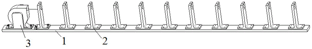
[0020] Such as figure 1 with figure 2 As shown, the present invention provides a calibration device for a wire displacement sensor, which includes a bottom plate 1 and a gauge block 2 . The base plate 1 has a sensor setting position for placing the stay wire displacement sensor, and the gauge block 2 is arranged on the base plate 1, and the gauge block 2 is located on one side of the sensor setting position.

[0021] Specifically, as figure 1 with figure 2 As shown, there are multiple gauge blocks 2, and all the gauge blocks 2 are on the same straight line as the set position of the sensor. ...


PUM


Abstract

The invention discloses a device and method for calibrating a stay wire displacement sensor. The calibration device includes a bottom plate and gauge blocks. A sensor setting position used for placing the stay wire displacement sensor is arranged on the bottom plate, and the gauge blocks are arranged on the bottom plate and are located at one side of the sensor setting position. The device for calibrating the stay wire displacement sensor is simple in structure and convenient to install, and can be used repeatedly, thereby improving calibration efficiency.

Description

technical field [0001] The invention belongs to the technical field of automobile product testing, in particular, the invention relates to a calibration device and a calibration method for a cable displacement sensor. Background technique [0002] In the process of automobile crash safety development test, the effective collapse of the pipe string can reduce the damage value of the chest and abdomen of the dummy. In order to check the collapse and energy absorption of the pipe string, it is necessary to use the cable displacement sensor to detect the dynamic collapse displacement of the pipe string. Quantity, to provide effective test data as a reference for later design. At the same time, in the seat belt dynamic test, both ECER16 and GB14166 require the measurement of the displacement of the dummy's chest and pelvis. It is necessary to use the cable displacement sensor to detect whether the displacement of the dummy's chest and pelvis meet the standard requirements during ...

Claims


Application Information

Patent Timeline
IPC IPC(8): G01B21/02
CPCG01B21/02
Inventor 徐丽刘正坤姚欣赵友梅魏复品沈光勇
Owner CHERY AUTOMOBILE CO LTD
Why Eureka
Try Eureka