
Missile hanger separation mechanism

A separation mechanism and hanging technology, which is applied in the direction of self-propelled bombs, projectiles, offensive equipment, etc., can solve the problems of low safety and difficult control of the hanging separation mechanism, achieve high synchronization of actions, improve flight safety, The effect of high space occupancy

Active Publication Date: 2015-11-18
JIANGXI HONGDU AVIATION IND GRP
View PDF7 Cites 7 Cited by
  • Summary
  • Abstract
  • Description
  • Claims
  • Application Information

AI Technical Summary

Problems solved by technology

[0004] In order to solve the technical problems that the existing missile hanging and separating mechanism is difficult to control and low in safety, the present invention proposes a missile hanging and separating mechanism. The connection is fixed to realize the load-carrying function of the suspension; after the missile is launched, the explosive bolt works first and is divided into two sections to disconnect the connection between the suspension and the missile body, and then the actuator works again to directly push the suspension to fly away from the missile body. Realize the separation function of hanging and projectile

Method used


Image

  • Missile hanger separation mechanism
  • Missile hanger separation mechanism
  • Missile hanger separation mechanism

Examples


Embodiment Construction

[0024] Embodiments of the present invention will be described in more detail below in conjunction with the accompanying drawings.

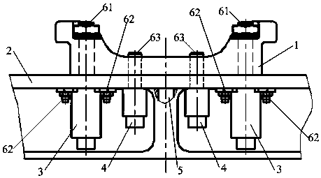
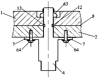
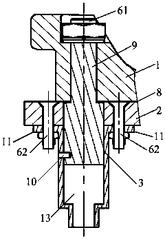
[0025] See attached Figures 1 to 4 , a missile suspension separation mechanism, including a suspension 1, an actuator 3, an explosive bolt 4, a projectile body 2 and a positioning pin 5, and one end of the actuator 3 is connected to the projectile body 2 through a second fastener 62 , the other end is connected to the hanger 1 through the first fastener 61; one end of the explosive bolt 4 is connected to the projectile body 2 through the fourth fastener 64, and the other end is connected to the hanger 1 through the third fastener 63; The hanger 1 is fixed on the body 2 through the positioning pin 5, and the surface of the body 2 in contact with the hanger 1 is a separation surface 8; the upper end of the explosion bolt 4 is provided with a "U"-shaped groove 12, so that The central plane of the "U"-shaped groove 12 is on the separation surface 8;...


PUM


Abstract

The invention discloses a missile hanger separation mechanism. The missile hanger separation mechanism comprises a hanger, an explosive bolt, an actuator, a missile body and a location pin, wherein one end of the actuator is connected with the missile body through a second fastener, and the other end of the actuator is connected with the hanger through a first fastener; one end of the explosive bolt is connected with the missile body through a fourth fastener, and the other end of the explosive bolt is connected with the hanger through a third fastener; the hanger is fixed on the missile body through the location pin, and the contact surface of the missile body and the hanger is a separation surface; a U-shaped groove is formed in the upper end of the explosive bolt, and the central plane of the U-shaped groove is located on the separation surface; and a push rod and a combustion cavity are arranged on and formed in the actuator, the combustion cavity is filled with gunpowder, and the push rod carries out initial locking through a shear pin. The missile hanger separation mechanism disclosed by the invention is simple and convenient to install and maintain, high in action synchronization of initiating explosive devices, and capable of effectively controlling the posture of the hanger after flying away from the missile body, and guaranteeing no collision of the hanger with the missile body during the process of flying away from the missile body, thus improving the flying safety of a carrying aircraft and a missile.

Description

technical field [0001] The invention belongs to the technical field of missile suspension, and in particular relates to a missile suspension separation mechanism. Background technique [0002] With the advancement of science and technology, new missiles are paying more and more attention to the influence of aerodynamic resistance on the range of the missile. While optimizing the aerodynamic shape, they have also begun to pay attention to the aerodynamic resistance caused by the suspension of the missile, especially the new stealth missile. In order to improve the range of the missile And stealth performance, after the missile is released, the suspension needs to be separated, and before the missile is released, the suspension needs to connect and transfer the load. [0003] The domestic hanger separation technology adopts the unlocking and separation scheme of explosive bolts. The hanger is connected to the missile body through the explosive bolts, and the hanger is directly...

Claims


Application Information

Patent Timeline
Patent Type & Authority Applications(China)
IPC IPC(8): F42B15/36
Inventor 洪厚全陈雷李玉亮李雁飞付俊兴孙英超林海彬郝桂珍
Owner JIANGXI HONGDU AVIATION IND GRP
Learn More