
Mixer

A technology of mixer and mixed gas, which is applied to machines/engines, adding non-fuel substances to fuel, internal combustion piston engines, etc., can solve the problems of engine design, manufacture, installation inconvenience, high cost, and adding engines, etc. Effects of reliability, performance improvement, and reduction of fluid flow resistance

Inactive Publication Date: 2015-11-18
GUANGXI YUCHAI MASCH CO LTD
View PDF8 Cites 24 Cited by
  • Summary
  • Abstract
  • Description
  • Claims
  • Application Information

AI Technical Summary

Problems solved by technology

However, these two mixers are generally designed and manufactured separately according to the current existing model, adding engine parts will bring a lot of inconvenience to the engine design, manufacture, installation, and after-sales use, and the cost is relatively high.

Method used


Image

  • Mixer
  • Mixer
  • Mixer

Examples


Embodiment Construction

[0024] The specific embodiments of the present invention will be described in detail below in conjunction with the accompanying drawings, but it should be understood that the protection scope of the present invention is not limited by the specific embodiments.

[0025] Unless expressly stated otherwise, throughout the specification and claims, the term "comprise" or variations thereof such as "includes" or "includes" and the like will be understood to include the stated elements or constituents, and not Other elements or other components are not excluded.

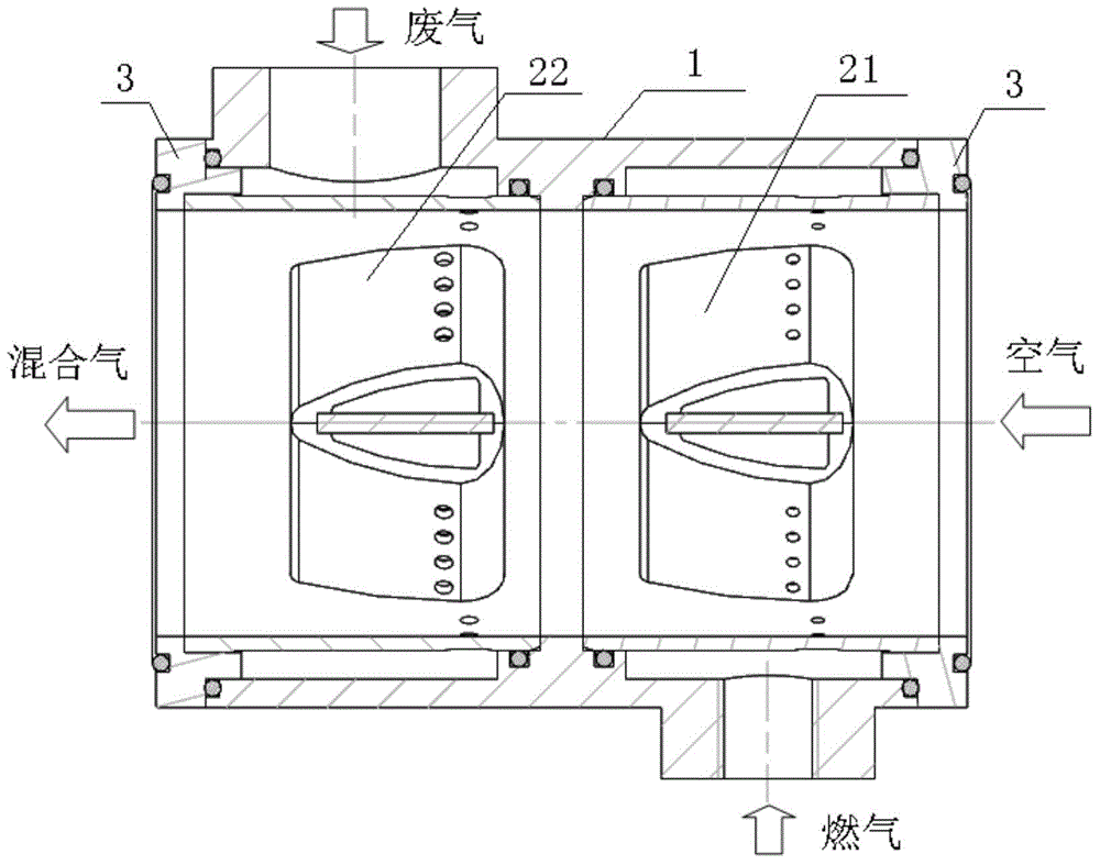
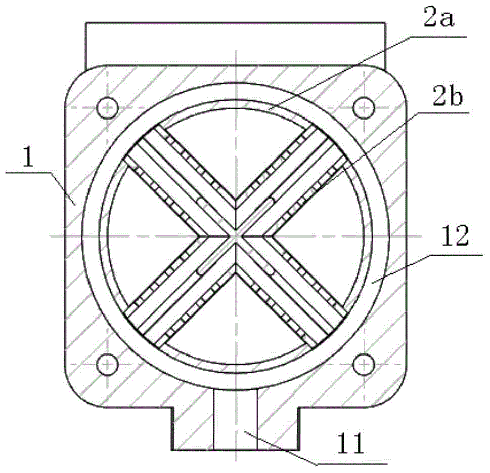
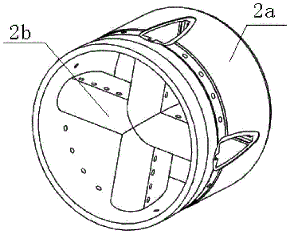
[0026] Such as figure 1 with figure 2 As shown, a mixer according to a specific embodiment of the present invention includes a cylindrical shell 1 , a gas mixing core 21 and an EGR mixing core 22 . One end of the cylindrical housing 1 is an air inlet, the other end of the cylindrical housing 1 is a mixed gas outlet, and the inside of the cylindrical housing 1 has a first chamber and a second chamber (not shown in the fig...


PUM


Abstract

The invention discloses a mixer which comprises a cylindrical shell, a fuel gas mixing core and an EGR mixing core. An air inlet is formed in one end of the cylindrical shell. A mixed gas outlet is formed in the other end of the cylindrical shell. A first cavity and a second cavity communicated with each other are formed in the cylindrical shell. A fuel gas inlet is formed in the side wall, close to the first cavity, of the cylindrical shell. A waste gas inlet is formed in the side wall, close to the second cavity, of the cylindrical shell. The fuel gas mixing core is sleeved with the first cavity. Fuel gas flowing through the fuel gas inlet and air flowing through the air inlet can enter the fuel gas mixing core so as to be mixed to form fuel gas mixed gas. The EGR mixing core is sleeved with the second cavity. The fuel gas mixed gas and waste gas flowing through the waste gas inlet can enter the EGR mixing core and are mixed and exhausted through the mixed gas outlet. By the adoption of the mixer, the integration of parts of an engine is effectively improved, the mixing evenness of fuel gas, air and waste gas in the gas engine is improved, and emission of harmful substances of the engine is reduced.

Description

technical field [0001] The invention relates to a power machine, in particular to a mixer. Background technique [0002] Harmful emissions from engines are a major source of air pollution. With the increasing importance of environmental protection, the goal of reducing harmful emissions from engines has become an important direction for engine development in the world today. Therefore, it is the primary task of all engine designers to carry out research on the control methods of engine harmful emissions. Among them, to reduce NO in engine exhaust x (nitrogen oxide) emissions, EGR (exhaust gas recirculation system) as a technical means can effectively reduce NO in exhaust emissions by delaying the combustion process and reducing the combustion temperature in the cylinder x content, has become an important technology for engine emission control, and is used by more and more engines. [0003] At present, the gas engines produced and sold on the market are mainly for National...

Claims


Application Information

Patent Timeline
Patent Type & Authority Applications(China)
IPC IPC(8): F02M25/07
CPCY02T10/12
Inventor 陶喜军覃玉峰公旭魏威盛利邓远海黄鸿叶洁唐兰张福
Owner GUANGXI YUCHAI MASCH CO LTD
Learn More