
Full-automatic stainless steel ring welding machine

A stainless steel ring, fully automatic technology, applied in welding equipment, laser welding equipment, welding/welding/cutting items, etc., can solve the problems of inability to meet the production requirements of steel strip welding, low machining accuracy of welding machines, and high maintenance costs , to achieve the effect of low maintenance cost, high machining accuracy and reduced maintenance cost

Inactive Publication Date: 2015-11-18
王贵文
View PDF5 Cites 16 Cited by
  • Summary
  • Abstract
  • Description
  • Claims
  • Application Information

AI Technical Summary

Problems solved by technology

[0002] Chinese Patent Publication No. 204036022U discloses a fully automatic cutting and welding machine for steel strips. The above-mentioned welding machine is an existing relatively advanced welding machine, but the above-mentioned welding machine needs to replace the mold when welding different steel strips, and the operation is more complicated. There will also be material jamming during production. Welding is also done with copper electrodes. During the welding process, the copper electrodes will gradually wear out, resulting in waste of excess materials. Moreover, the above-mentioned welding machines have low processing accuracy and low production efficiency. There are not many, and the maintenance cost is high, which cannot meet the welding production needs of steel strips

Method used


Image

  • Full-automatic stainless steel ring welding machine
  • Full-automatic stainless steel ring welding machine
  • Full-automatic stainless steel ring welding machine

Examples


Embodiment Construction

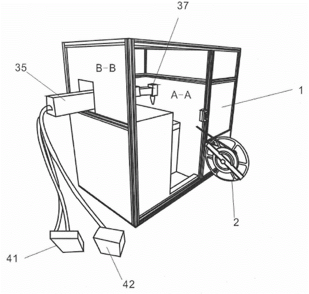
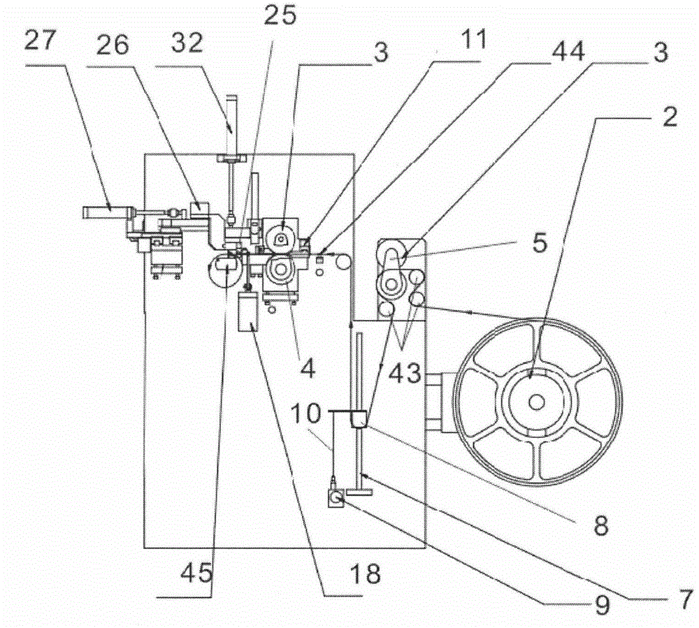
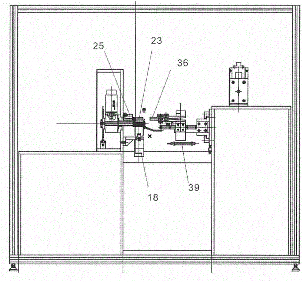
[0026] like Figure 1 to Figure 3 As shown, the fully automatic stainless steel ring welding machine provided by the present invention includes a body 1, a steel belt transmission processing device and a steel belt laser welding device fixed on both sides of the body 1. The material tray 2, the steel belt primary drive, the material storage device, the steel belt secondary drive, the steel belt guide device, the steel belt coiling device and the material cutting device fixed on the inside of the body 1, the above-mentioned steel belt primary drive and steel belt two The secondary drive is set up and down by the rubber wheel 3 and the steel wheel 4, and a pull rod 5 is fixed on the outside of the two, and the adjustment wrench 6 is fixed on the pull rod 5. The steel belt is fixed close to the material tray 2 for the primary drive, and is provided by the storage drive motor. Power, the secondary drive of the steel belt is driven by a servo motor. The above-mentioned storage devi...


PUM


Abstract

The invention relates to a full-automatic stainless steel ring welding machine. Previous copper welding is replaced by laser welding; waste of welding materials is avoided during welding; welded positions of a steel ring are flat; the quantity of consumed materials is small; due to extremely high steel belt feeding requirements of laser welding, steel belt driving and steel belt guiding devices and cutting devices are also correspondingly improved. For example, rubber wheels and steel wheels cooperate so that material feeding accuracy is increased; the friction force is extremely large when all wheels are the rubber wheels, and skidding is prone to occur when all wheels are the steel wheels; a stay wire encoder is designed for performing frequency conversion on a material storage driving motor so as to control the rotating speed of the motor and stable material storage is achieved; a steel belt can pull a sliding block to move upwards when operating quickly, and the rotating speed of the material storage driving motor is correspondingly increased; besides, multiple groups of steel belt guiding devices adopt servo motors for transmission in order to increase transfer accuracy, and cutting heads, winding mechanisms and welding structures are correspondingly improved.

Description

technical field [0001] The invention relates to a fully automatic welding machine, in particular to a fully automatic stainless steel ring welding machine. Background technique [0002] Chinese Patent Publication No. 204036022U discloses a steel strip ring automatic cutting and welding machine. The above-mentioned welding machine is an existing relatively advanced welding machine, but the above-mentioned welding machine needs to replace the mold when welding different steel strips, which is complicated to operate. There will also be a phenomenon of material jamming in production, and copper electrode welding is also used for welding. During the welding process, the copper electrode will be gradually lost, resulting in waste of excess materials. Moreover, the above-mentioned welding machine has low machining accuracy, low production efficiency, and low function. There are not many, and the maintenance cost is high, which cannot meet the welding production needs of steel strip...

Claims


Application Information

Patent Timeline
IPC IPC(8): B23K26/26B23K26/70B23K101/30
CPCB23K26/0093B23K26/26B23K2101/30
Inventor 王贵文
Owner 王贵文
Learn More