
Electrode for projection welding of resistor

An electrode technology for projection welding, applied in the field of electrodes, can solve the problems of partial damage to the grip rod and the lower electrode, increase the cost of consumables and spare parts management, reduce the service life of the grip rod, etc., to avoid faster wear and tear, Efforts to reduce management burden and improve cooling effect

Active Publication Date: 2015-11-18
DIGITAL DIE STAMPING TECH WUHAN
View PDF8 Cites 1 Cited by
  • Summary
  • Abstract
  • Description
  • Claims
  • Application Information

AI Technical Summary

Problems solved by technology

[0002] The electrode used in the resistance projection welding nut is composed of five parts: the electrode handle, the lower electrode seat, the electrode cover, the positioning pin, and the upper electrode; there are the following defects during use: First, due to the lower electrode seat The cooling effect of circulating water on the actual working surface (electrode cover) is not good, resulting in faster wear of the electrode cover; second, due to the large number of electrode parts, it needs to be replaced every time welding nuts of different specifications are replaced. Frequent disassembly of the entire lower electrode assembly will damage the mating part of the handle and the lower electrode, reducing the service life of the handle; third, the electrode assembly currently used increases the cost of consumables and spare parts management due to the large number of components. while burdening management

Method used


Image

  • Electrode for projection welding of resistor
  • Electrode for projection welding of resistor
  • Electrode for projection welding of resistor

Examples


Embodiment Construction

[0021] The principles and features of the present invention are described below in conjunction with the accompanying drawings, and the examples given are only used to explain the present invention, and are not intended to limit the scope of the present invention.

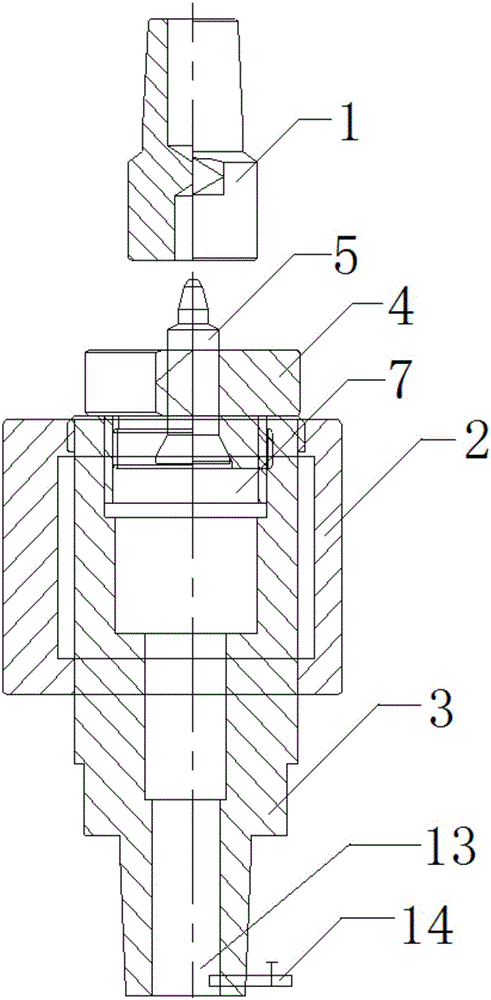
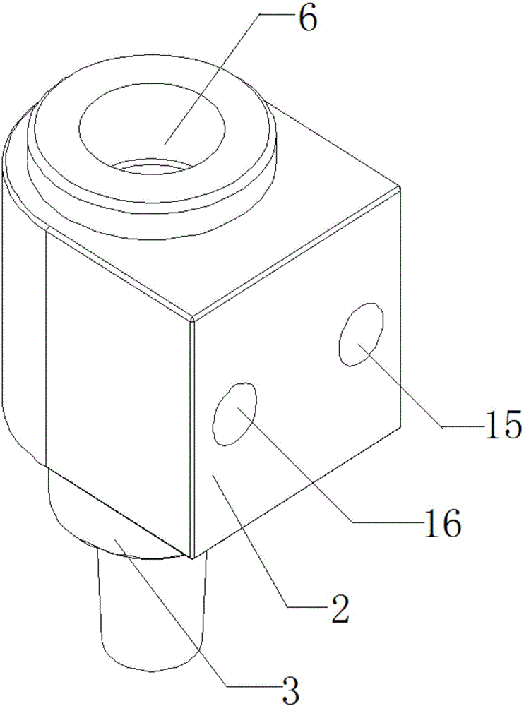
[0022] Such as figure 1 As shown, an electrode for resistance projection welding includes an upper electrode assembly and a lower electrode assembly, the upper electrode assembly includes an upper electrode 1, and the lower electrode assembly includes a circulating water cooling block 2, an electrode handle 3, and an electrode cover 4 and positioning pin 5; the structure of the circulating water cooling block 2 is as figure 2 and image 3 As shown, the circulating water cooling block 2 is provided with a cooling hole 6, the connecting block 7 is embedded in the cooling hole 6, the top end of the electrode handle 3 is embedded in one end of the cooling hole 6, the The structure of the electrode cover is as Figur...


PUM


Abstract

The invention relates to an electrode for projection welding of a resistor. The electrode comprises an upper electrode assembly and a lower electrode assembly. The upper electrode assembly comprises an upper electrode body. The lower electrode assembly comprises a circulation water cooling block, an electrode holder, an electrode cover and a positioning pin. The circulation water cooling block is provided with a cooling hole, a connecting block is embedded in the cooling hole, and the top end of the electrode holder is embedded in one end of the cooling hole. The electrode cover comprises a cover body and a base, the base of the electrode cover is embedded in the other end of the cooling hole, and the top end of the electrode holder is connected with the base of the electrode cover through the connecting block. The positioning pin comprises a positioning body and a positioning head, the positioning body is embedded in the electrode cover, and the positioning head corresponds to the upper electrode body. By means of the electrode for projection welding of the resistor, the cooling effect of the electrode cover is improved, damage to the electrode holder is avoided, the use cost of the electrode assemblies can be saved, and management burden is relieved.

Description

technical field [0001] The invention relates to an electrode, in particular to an electrode for resistance projection welding. Background technique [0002] The electrode used in the resistance projection welding nut is composed of five parts: the electrode handle, the lower electrode seat, the electrode cover, the positioning pin, and the upper electrode; there are the following defects during use: First, due to the lower electrode seat The relationship between the cooling circulating water and the actual working surface (electrode cover) cooling effect is not good, resulting in faster wear of the electrode cover; second, because there are many electrode parts, each time when replacing the welding nut of different specifications, it needs to be replaced Frequent disassembly of the entire lower electrode assembly will damage the mating part of the handle and the lower electrode, reducing the service life of the handle; third, the electrode assembly currently used increases t...

Claims


Application Information

Patent Timeline
IPC IPC(8): B23K11/30B23K11/14
CPCB23K11/14B23K11/30
Inventor 王玉辉李虎林
Owner DIGITAL DIE STAMPING TECH WUHAN
Learn More