Stirring shaft mounting structure of stirring device

A stirring device and installation structure technology, applied in the direction of mixer accessories, dissolving, mixing machines, etc., can solve problems such as the loosening of the stirring shaft, and achieve the effect of firm installation and good bearing capacity

Inactive Publication Date: 2015-11-18
CHONGQING YUKUNLONG METALLURGICAL MATERIAL CO LTD
View PDF0 Cites 1 Cited by
  • Summary
  • Abstract
  • Description
  • Claims
  • Application Information

AI Technical Summary

Problems solved by technology

The stirring device usually includes a stirring barrel, a stirring shaft, and a stirring blade. The stirring shaft is generally installed on the stirring barrel through a bearing. During the stirring process, the stirring blade will exert axial and radial forces on the stirring shaft along the stirring shaft. It is easy to cause the stirring shaft to loosen

Method used


Image

  • Stirring shaft mounting structure of stirring device

Examples


Embodiment 1

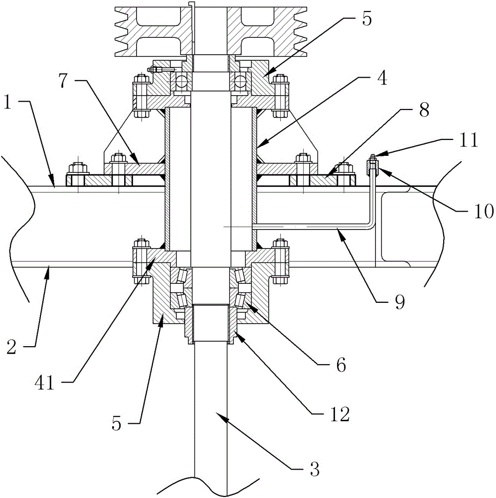
[0019] The embodiment is basically as attached figure 1 Shown: a stirring shaft installation structure of a stirring device, including a stirring shaft 3 and a mixing barrel, a support seat 7, a bearing seat 5 and a connecting cylinder 4 with flanges 41 at both ends, and the stirring barrel is provided with upper and lower The first mounting plate 1 and the second mounting plate 2 are arranged, the connecting cylinder 4 runs through the first mounting plate 1 and the second mounting plate 2, the support base 7 is connected to the first mounting plate 1 by bolts, and the support base 7 is connected to the first mounting plate 2. An anti-vibration pad 8 is provided between the mounting plate 1, flange-connected bearing housings 5 ​​are installed at the upper and lower ends of the connecting cylinder 4 respectively, the bearing housing 5 at the upper end of the connecting cylinder 4 is connected to the supporting base 7 by bolts, and the stirring shaft 3 runs through The connecti...

Embodiment 2

[0023] The difference from Embodiment 1 is that the sealing structure is a sealing plug matched with the oil injection pipe 9 . The structure of sealing with a sealing plug is simple.

[0024] Specific working principle:

[0025] Let’s take Embodiment 1 as an example to illustrate: when installing, firstly insert the stirring shaft 3 into the connecting cylinder 4, respectively install the bearings into the bearing housing 5, and then connect the corresponding bearing housings 5 ​​to the upper and lower ends of the connecting cylinder 4 respectively. Then connect the support seat 7 to the first mounting plate 1, and penetrate the connecting cylinder 4 into the first mounting plate 1 and the second mounting plate 2, and finally connect the bearing seat 5 on the upper end of the connecting cylinder 4 to the supporting seat 7 can be connected. This program is additionally equipped with a connecting cylinder 4 and a support seat 7. The bearing seat 5 mainly bears force through t...


PUM


Abstract

The invention discloses a stirring shaft mounting structure of a stirring device. The stirring shaft mounting structure comprises a stirring shaft and a stirring barrel, and also comprises a supporting seat, bearing seats and a connecting cylinder with two ends provided with flange discs, the stirring barrel is provided with a first mounting plate and a second mounting plate which are arranged up and down, the connecting cylinder penetrates through the first mounting plate and the second mounting plate, the supporting seat is connected to the first mounting plate, the upper end and the lower end of the connecting cylinder are respectively in flange connection with the bearing seats, the bearing seat at the upper end of the connecting cylinder is connected to the supporting seat, the stirring shaft penetrates through the connecting cylinder and the bearing seats, the stirring shaft is connected with the bearing seats through bearings, and the bearing close to the second mounting plate is a tapered roller bearing. The connecting structure in the above scheme realizes firm mounting of the stirring shaft.

Description

technical field [0001] The invention belongs to the field of stirring machinery, and in particular relates to a stirring shaft installation structure of a stirring device. Background technique [0002] In continuous casting production, besides pouring billets with small cross-sections, mold flux is mostly used. Practice has proved that this process is one of the important conditions to ensure the quality and normal operation of the billet. In the early 1970s, this process was successfully used in continuous casting of slabs in my country, which solved the problem of longitudinal cracking of slabs, and then it was gradually popularized and applied. In recent years, a series of mold fluxes have been established successively, and some mold fluxes for continuous casting special steel have been developed, which have created necessary conditions for the further development of continuous casting in my country. Mold slag has the following functions: 1. Heat insulation and heat pre...

Claims


Application Information

Patent Timeline
IPC IPC(8): B01F15/00
Inventor 罗静李炎清廖光权
Owner CHONGQING YUKUNLONG METALLURGICAL MATERIAL CO LTD
Why Eureka
Try Eureka