Shaft support structure for belt-type stepless transmission

A technology of continuously variable transmissions and bearings, which is applied to components with teeth, belts/chains/gears, transmissions, etc., which can solve the problems of increased displacement and length, and achieve the effect of improving rigidity

Inactive Publication Date: 2015-11-11
TOYOTA JIDOSHA KK
View PDF9 Cites 2 Cited by
  • Summary
  • Abstract
  • Description
  • Claims
  • Application Information

AI Technical Summary

Problems solved by technology

However, even if the position of the bearing is changed in this way to shorten the distance between the position where the load is applied to the input shaft and the output shaft and the bearing, the deflection deformation of the input shaft and the output shaft will not occur much.
As a result, the length of the portion extending outward from between the bearings in the axial direction becomes longer, and the amount of displacement of this portion in the radial direction may increase.

Method used


Image

  • Shaft support structure for belt-type stepless transmission
  • Shaft support structure for belt-type stepless transmission
  • Shaft support structure for belt-type stepless transmission

Examples


Embodiment Construction

[0027] Next, the configuration of a power transmission device including a belt-type continuously variable transmission targeted by the present invention will be described. Figure 6 It is a frame diagram for explaining an example of the structure of this power transmission device. Figure 6 The illustrated power transmission device has a power source 1 such as an engine or a motor. In addition, a hybrid drive device including an engine and a motor may be used as the power source 1 . In addition, in the example described below, the engine 1 is used as a power source.

[0028] A torque converter 3 is connected to an output shaft 2 of the engine 1 . The torque converter 3 is configured to transmit power through a fluid flow and to amplify and output torque in a converter region where the rotational speed on the input side is higher than the rotational speed on the output side, similarly to conventionally known torque converters. In addition, the torque converter 3 is provided ...


PUM


Abstract

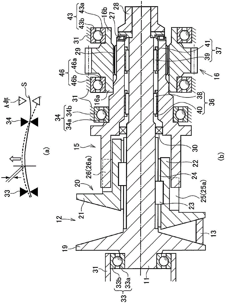
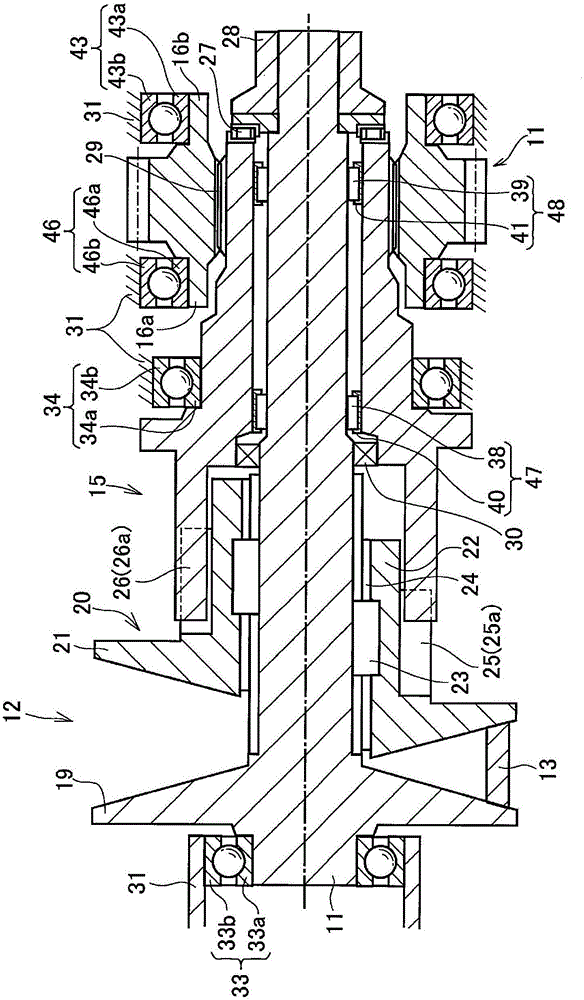
Provided is a shaft support structure for a belt-type stepless transmission, the shaft support structure being configured so that the length of a shaft on which a torque cam is provided can be reduced. A first bearing (36), which supports both a rotating shaft (11) and a torque cam (15) so that the rotating shaft (11) and the torque cam (15) can rotate relative to each other, is provided between the outer peripheral surface of the rotating shaft (11) and the inner peripheral surface of the torque cam (15). A second bearing (42), which rotatably supports one axial end of an output member (16) on a case (31), is provided on the outer peripheral side of the first bearing (36) in the radial direction. A space is formed at a position on the inner peripheral side of the second bearing (42) and on the outer peripheral side of the torque cam (15). A seal member (32) which is fitted to the outer peripheral surface of the torque cam (15) is installed in the space.

Description

technical field [0001] The present invention relates to a shaft support structure in a belt-type continuously variable transmission whose torque transmission capacity changes according to the clamping force clamping the belt, and more particularly to a belt-type continuously variable transmission configured to suppress displacement of the shaft due to a load received from the belt shaft bearing structure. Background technique [0002] Japanese Patent Application Laid-Open No. 2001-330089 describes a belt-type continuously variable transmission configured to generate a thrust force for clamping a belt by a hydraulic actuator. In this belt-type continuously variable transmission, one end portion of the input shaft is formed in a hollow shape, and a rotating shaft integrated with a carrier constituting a front-rear travel switching mechanism is fitted in the hollow portion. Therefore, when the teeth formed on the inner wall surface of the hollow portion mesh with the teeth for...

Claims


Application Information

Patent Timeline
Patent Type & Authority Applications(China)
IPC IPC(8): F16H9/18F16H57/021F16H57/029F16H57/035
CPCF16H57/035F16H37/022F16H55/56F16H57/021F16H9/18F16H57/029
Inventor 田渊元树柴田直之伊地知彬荒川一哉
Owner TOYOTA JIDOSHA KK
Why Eureka
Try Eureka