
Active optical module multi-channel automatic test system and method

An automatic test system and optical module test technology, applied in the direction of transmission monitoring/testing/fault measurement system, can solve the problems of high labor and equipment costs, low test efficiency, etc., to save equipment expenses, improve test accuracy and reliability Effects of traceability and utilization improvement

Active Publication Date: 2015-11-11
GUANGXUN SCI & TECH WUHAN
View PDF8 Cites 53 Cited by
  • Summary
  • Abstract
  • Description
  • Claims
  • Application Information

AI Technical Summary

Problems solved by technology

[0004] In order to solve the above-mentioned problems of high labor and equipment cost and low test efficiency of optical module testing, the present invention provides a multi-channel automatic testing system and method for active optical modules. The testing system realizes automatic testing of optical modules. Up to 8 modules can be tested at the same time, which greatly improves production efficiency and reduces labor costs; multiple test modules use one oscilloscope in time-sharing, which improves the utilization rate of valuable equipment and saves equipment expenses; the test system automatically collects and Record test results instead of manual work, improving test accuracy and traceability

Method used


Image

  • Active optical module multi-channel automatic test system and method
  • Active optical module multi-channel automatic test system and method
  • Active optical module multi-channel automatic test system and method

Examples


Embodiment Construction

[0032] In order to make the object, technical solution and advantages of the present invention clearer, the present invention will be described in further detail below in conjunction with the embodiments and accompanying drawings. Here, the exemplary embodiments and descriptions of the present invention are used to explain the present invention, but not to limit the present invention.

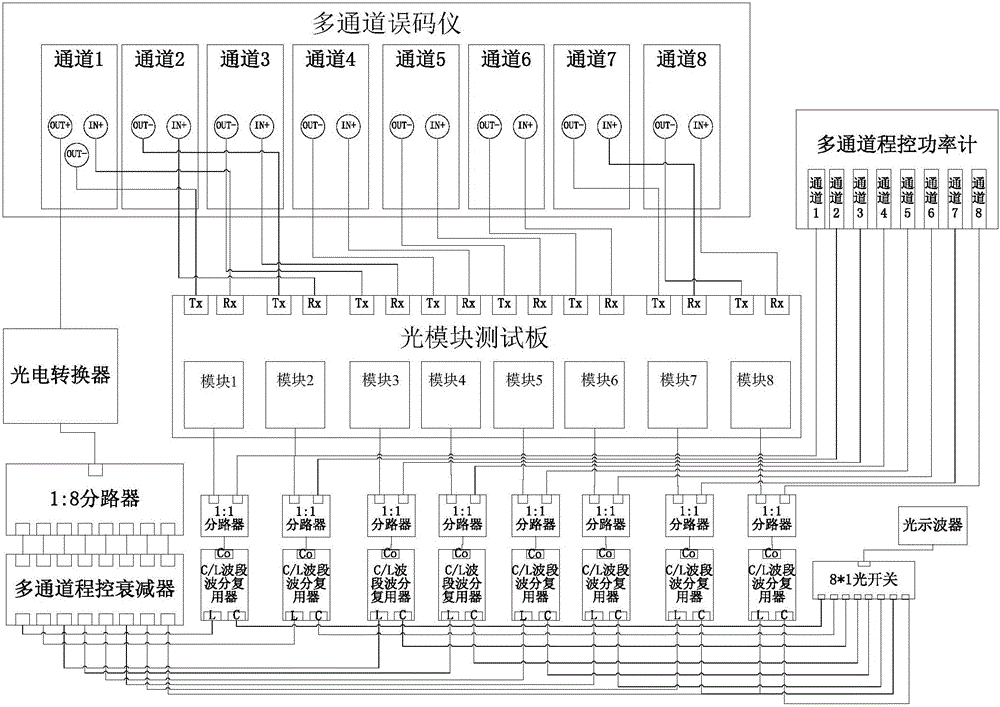
[0033] An active optical module multi-channel automatic test system provided by the present invention, its optical path is as follows figure 1 As shown, the test system includes an electro-optical converter, a light source splitter (1:N splitter), a multi-channel programmable attenuator, a C / L wavelength division multiplexer, a programmable optical switch, an optical oscilloscope, and a multi-channel programmable optical Power meter, optical module test board, and test control host ( figure 1 Not shown in ), wherein N is a positive integer greater than 2, preferably 8. The program-controlled ...


PUM


Abstract

The invention provides an active optical module multi-channel automatic test system and a method. optimal signals emitted by a tested optical module are monitored, and indexes of the incident light power, emission current, bias current, temperature, voltage, extinction ratio, eye diagram allowance, crossing point, OMA (optical modulation amplitude) etc. are measured and calculated; if the above indexes are all in accordance with the standard, the sensitivity of the optical module is tested, the emission optical power of the tested module is enabled to reach the sensitivity of the test standard via the adjustment of an attenuator, and error code tests are conducted; and if there is no error code, indexes of alarm value and alarm recovery etc. of the optical module are tested. According to the test system, an error detector, an optical module test board, an optical power meter, and the attenuator employed by the test system are all multi-channel devices, an optical switch and an optical splitter are combined for time-sharing multiplexing of one oscilloscope, at least 8 modules can be simultaneously tested, the utilization rate of the oscilloscope and the test efficiency of the optical module are greatly optimized, the equipment cost and the manual cost are reduced, and automatic and batch production of the optical modules is realized.

Description

technical field [0001] The invention relates to an optical communication device testing technology, in particular to an automatic testing method and system for an active optical module, in particular a testing system capable of automatically testing eight or more active optical modules simultaneously and asynchronously. Background technique [0002] With the progress and development of the information age, the optical module is the basis of all information products and occupies a pivotal position. Its huge market demand and high-precision index requirements force the testing efficiency and accuracy of the optical module to be improved. The traditional test method of the optical module is to place the module under test in the test board fixture, monitor the emission current, bias current, temperature, voltage and other indicators of the module under test; read and calculate the extinction ratio, cross point, eye Figure margin, OMA and other indicators; adjust the attenuator t...

Claims


Application Information

Patent Timeline
Patent Type & Authority Applications(China)
IPC IPC(8): H04B10/07
Inventor 张小娇曾诚贾昉谭书伟胡毅周治柱
Owner GUANGXUN SCI & TECH WUHAN
Learn More