
Cylindrical permanent magnet system for focusing and guiding electron beam

A permanent magnet, cylindrical technology, applied in the field of permanent magnet systems, can solve the problems of slow response time and complex system, and achieve the effect of avoiding defocusing

Inactive Publication Date: 2015-11-11
INST OF ELECTRICAL ENG CHINESE ACAD OF SCI
View PDF7 Cites 12 Cited by
  • Summary
  • Abstract
  • Description
  • Claims
  • Application Information

AI Technical Summary

Problems solved by technology

[0005] The purpose of the present invention is to overcome the disadvantages of slow response time and complex system in the prior art, and propose a cylindrical permanent magnet system for focusing and guiding electron beams

Method used


Image

  • Cylindrical permanent magnet system for focusing and guiding electron beam
  • Cylindrical permanent magnet system for focusing and guiding electron beam
  • Cylindrical permanent magnet system for focusing and guiding electron beam

Examples


Embodiment 1

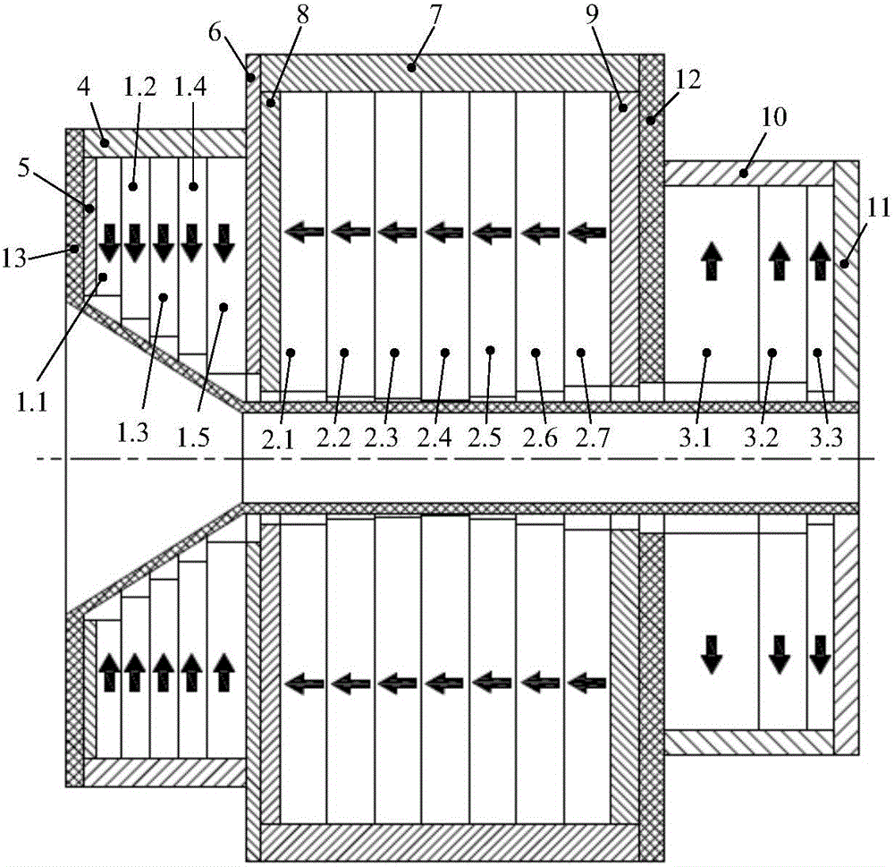
[0031]Embodiment 1 is also composed of multiple magnetic ring structures. The difference between embodiment 2 and embodiment 1 is that the inner cylinder 13 of the magnet has a tapered hole structure at the end, which can meet the requirements of microwave tube devices with special requirements on the end.

[0032] The first permanent magnet 1, the second permanent magnet 2 and the third permanent magnet 3 in Embodiment 1 and Embodiment 2 work in a demagnetized state, and most of the magnetic force lines emitted by the first permanent magnet 1 pass through the magnet inner cylinder in the axial direction The inner hole air gap of 13 enters the third permanent magnet 3, and the magnetic flux emitted by the second permanent magnet is used to compress the magnetic flux passing through the uniform region 14, thereby generating an axial magnetic field of 0.5-1.2T in the uniform region 14. The permanent magnet system of embodiment 2 can produce the axial magnetic field of 0.88T in t...


PUM


Abstract

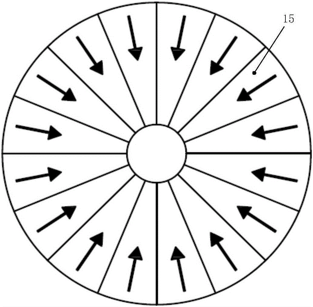
The invention provides a cylindrical permanent magnet system for focusing and guiding an electron beam. The cylindrical permanent magnet system comprises a first permanent magnet (1), a second permanent magnet (2), a third permanent magnet (3), an inner magnet cylinder (13), an outer cylinder of supporting three permanent magnets, and flanges, wherein the flanges are distributed at two ends of each of the first permanent magnet (1), the second permanent magnet (2) and the third permanent magnet (3); the three permanent magnets are supported and fixed on the outer cylinder and are connected with one another through the flanges; the magnetizing direction of the first permanent magnet (1) points to the axis of the first magnet along the radial direction; the magnetizing direction of the second permanent magnet (2) points to the first magnet (1) along the axial direction; the magnetizing direction of the third permanent magnet (3) deviates from the axis of the third magnet along the radial direction; the three permanent magnets are composed of multiple layers of magnet rings; and each magnet ring is formed by splicing fan-shaped magnetic steel. The dimensions, the positional relationship and gradient change of inner diameters of the three permanent magnets are adjusted, so that the axial magnetic field which meets different magnetic field translocation and uniformity requirements can be obtained.

Description

technical field [0001] The invention relates to a permanent magnet system, in particular to a cylindrical permanent magnet system for focusing and guiding electron beams. Background technique [0002] The basic principle of the microwave tube is to convert the energy of the electron beam into microwave or millimeter wave energy by using the interaction between the electron beam and the high-frequency electromagnetic field. In order to limit the lateral spread of the electron beam, an external static magnetic field is needed to focus and guide the electron beam. The magnetic field position, magnetic field uniformity and magnetic field strength of the external magnetic field directly affect the quality of the electron beam in the microwave tube. High-power microwave tubes mainly include high-power gyrotron devices, relativistic return wave tubes, etc., which can generate output powers ranging from tens of kilowatts to several gigawatts, and require a strong static magnetic fi...

Claims


Application Information

Patent Timeline
IPC IPC(8): H01F7/02
Inventor 李兰凯王秋良戴银明王晖王厚生程军胜李毅崔春艳
Owner INST OF ELECTRICAL ENG CHINESE ACAD OF SCI
Learn More