
Multi-return-stroke gas-steam boiler

A gas steam, multi-return technology, applied in steam boilers, fire tube steam boilers, steam generation and other directions, can solve the problems of low gas combustion efficiency, short flue gas flow, slow combustion speed, etc., to improve utilization, reduce Flame temperature, improved combustion effect

Active Publication Date: 2015-11-11
ZHEJIANG SHANGNENG BOILER
View PDF6 Cites 7 Cited by
  • Summary
  • Abstract
  • Description
  • Claims
  • Application Information

AI Technical Summary

Problems solved by technology

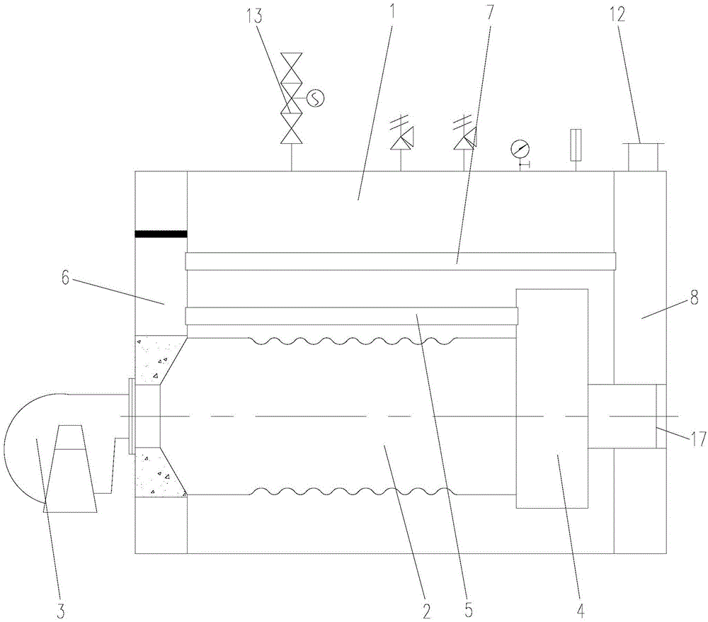
like figure 2 As shown, the existing gas-fired steam boiler structure usually adopts a horizontal fast-installed internal combustion three-pass fire tube boiler, and generally uses a diffusion burner for combustion. Natural gas and air are not pre-mixed, but mixed by diffusion after spraying into the furnace. Combustion while diffusing, the combustion speed is slow and the flame is long, resulting in insufficient combustion. At the same time, the flue gas temperature in the furnace is too high, the concentration of nitrogen oxides is high, and the gas combustion efficiency is low
The flame produced by the burner passes through the furnace, enters the combustion chamber, passes through the first return pass, the second return pass through the smoke pipe, and then is discharged into the atmosphere from the rear smoke chamber through the chimney. Due to the short flow of flue gas and the high temperature of the exhaust gas, it causes waste of energy

Method used


Image

  • Multi-return-stroke gas-steam boiler
  • Multi-return-stroke gas-steam boiler

Examples


Embodiment Construction

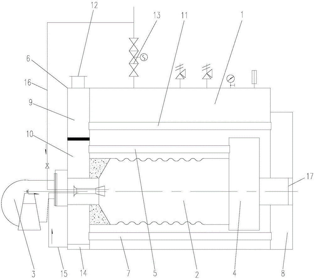
[0010] Such as figure 1 As shown, the present invention discloses a multi-return gas-fired steam boiler, comprising a furnace chamber 1, a furnace chamber 2 is provided at the bottom of the furnace chamber 1, a burner 3 is connected to the front end of the furnace chamber 2, and the furnace chamber 2 The top of the furnace has a steam outlet 13, and the end of the furnace 2 has a combustion chamber 4, and the combustion chamber 4 has an explosion-proof door 17, and the upper part of the combustion chamber 4 communicates with the second return smoke pipe 5, The other end of the two-pass smoke pipe 5 communicates with the front smoke box 6 at the front end of the furnace 2, and the front smoke box 6 communicates with the rear smoke box 8 at the end of the furnace 2 through the three-pass smoke pipe 7, and the burner 3. After the injected gas is mixed with air, it burns in the furnace 2, and the high-temperature flue gas formed by the combustion flows through the back-burning ch...


PUM


Abstract

The invention discloses a multi-return-stroke gas-steam boiler. The multi-return-stroke gas-steam boiler comprises a hearth. The front end of the hearth is connected with a burner. A steam outlet is formed in the top of the hearth. The upper portion of a backdraft chamber at the tail end of the hearth is communicated with a second-return-stroke smoke pipe. The other end of the second-return-stroke smoke pipe is communicated with a front smoke box. The front smoke box is communicated with a rear smoke box through a third-return-stroke smoke pipe. The front smoke box is divided into an upper front smoke box and a lower front smoke box. The third-return-stroke smoke pipe is communicated with the lower front smoke box. The rear smoke box and the upper front smoke box are communicated through a fourth-return-stroke smoke pipe. An annular air box is arranged on the periphery of the front smoke box and communicated with an inlet of the hearth through a hot air pipe. The steam outlet is communicated with the inlet of the hearth through a steam pipe. The fourth-return-stroke smoke pipe and the annular air box are additionally arranged, a proper amount of high-temperature steam is injected, so that burning in the hearth is improved, the maximal flame temperature is reduced, and therefore high-temperature oxynitride is reduced, the efficiency of the boiler is greatly improved, and meanwhile emission of harmful gas is reduced.

Description

technical field [0001] The invention relates to a gas-fired steam boiler, in particular to a gas-fired steam boiler which adopts four-pass structure, combustion pre-mixing technology and steam injection technology. Background technique [0002] With the implementation of coal-to-gas boilers, coal-fired steam boilers are about to be eliminated, and gas-fired steam boilers are becoming more and more widely used. Such as figure 2 As shown, the existing gas-fired steam boiler structure usually adopts a horizontal fast-installed internal combustion three-pass fire tube boiler, and generally uses a diffusion burner for combustion. Natural gas and air are not pre-mixed, but mixed by diffusion after spraying into the furnace. Burning while diffusing, the burning speed is slow and the flame is long, resulting in insufficient combustion. At the same time, the flue gas temperature in the furnace is too high, the concentration of nitrogen oxides is high, and the combustion efficiency o...

Claims


Application Information

Patent Timeline
IPC IPC(8): F22B31/08F22B9/12F23L15/00F23L7/00
CPCY02E20/34
Inventor 陆泳邓芝平徐孝明张李鑫
Owner ZHEJIANG SHANGNENG BOILER
Learn More