
Micro oil cylinder

A kind of oil cylinder and miniature technology, applied in the direction of fluid pressure actuation device, etc., can solve the problems of high processing cost, long order cycle, complicated process, etc., and achieve the effect of low processing cost, high working reliability and simple process

Inactive Publication Date: 2015-11-11
CHINA NORTH VEHICLE RES INST
View PDF12 Cites 1 Cited by
  • Summary
  • Abstract
  • Description
  • Claims
  • Application Information

AI Technical Summary

Problems solved by technology

HOERBIGER has products abroad, but its product structure is relatively complicated, requiring deep and long holes and oblique holes to be drilled in the cylinder wall. The process is complicated, the processing cost is high and the weight is heavy. In addition, the order cycle is long and the price is expensive.

Method used


Image

  • Micro oil cylinder
  • Micro oil cylinder
  • Micro oil cylinder

Examples


Embodiment 1

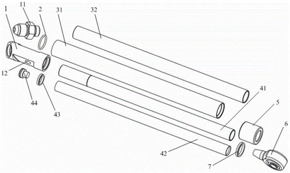
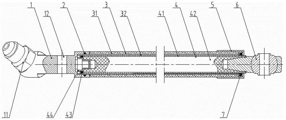
[0033] Such as Figure 1-Figure 3 As shown, the present embodiment provides a miniature oil cylinder, which mainly includes an end cover 1, a composite cylinder barrel 3, a composite plunger rod 4, a fixed end cover 5, and rod end bearings 6. The miniature oil cylinder is a single The action cylinder relies on the oil pressure to push the composite plunger rod 4 outward when it is loaded. After unloading, the composite plunger rod 4 is recovered to the inside of the composite cylinder 3 under the action of external force, thereby completing a working process.

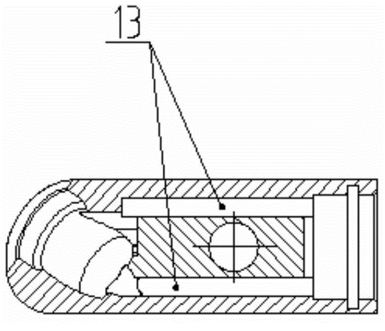
[0034] When loaded, the pressure oil of the hydraulic system enters from the joint 11 on the end cover 1, enters the rodless chamber of the miniature oil cylinder through the two oil passages 13 inside the end cover 1, and the pressure oil pushes the composite plunger rod 4 and the rod end bearing 6. Stretch out gradually along the inner wall of the composite cylinder 3 until the end point, and finally complete a stretc...

Embodiment 2

[0042] The miniature oil cylinder provided in this embodiment adopts new composite materials and new structural technology, and is mainly composed of end caps, composite cylinder barrels, composite plunger rods, fixed end caps, rod end bearings and related seals.

[0043] There are two oil passages, through holes and joints on the end cover, and the two inner oil passages are used for oil in and out, and the through hole left in the middle of the end cover is used to pass through the pin shaft to install and fix the miniature oil cylinder. The end cover is threadedly connected with the joint, and the installation joint surface is an inclined plane, which is designed to facilitate the installation and layout of the oil pipe. The joint is the only oil inlet and outlet port of the miniature oil cylinder; the composite cylinder is mainly composed of the cylinder casing and the cylinder , The cylinder casing is made of high-strength carbon fiber composite material, the cylinder is mad...


PUM


Abstract

The invention belongs to the technical field of mechanical equipment, and particularly relates to a micro oil cylinder. The micro oil cylinder comprises an end cover, a composite cylinder barrel, a composite plunger rod, a fixed end cover, a rod end bearing, a sealing ring and a dustproof ring. The composite cylinder barrel is formed by compounding a stainless steel cylinder barrel outer sleeve and a cylinder barrel outer sleeve made of a carbon fiber material; the composite plunger rod is formed by compounding a stainless steel plunger rod steel sleeve and an internal carbon fiber rod; the composite plunger rod and the rod end bearing are bonded together for bearing movement; an oil path is formed in the end cover for passing through oil; and a through hole is formed in the end cover for allowing a pin roll to penetrate through, so that the pin roll is fixedly mounted. The micro oil cylinder is a single-action cylinder; during bearing, the composite plunger rod is pushed by virtue of pressure oil in a rodless cavity to move along an inner hole of the composite cylinder barrel; the composite plunger rod is mainly used for bearing pressure stress; and during unloading, the composite plunger rod is gradually shrunk into the composite cylinder barrel along the inner hole of the composite cylinder barrel under action of external force. The micro oil cylinder disclosed by the invention adopts a novel structure, a novel composite material concept, a novel structure and a novel appearance. The process is simple, the weight is small and the cost is low.

Description

technical field [0001] The invention belongs to the technical field of mechanical equipment, and in particular relates to a miniature oil cylinder. Background technique [0002] Based on the miniature oil cylinder to achieve a specific load-bearing drive function, it is currently widely used in the fields of CNC machine tools, medical equipment and robots. As a non-standard component, the miniature oil cylinder has not yet been processed and sold by domestic manufacturers. HOERBIGER has products abroad, but its product structure is relatively complex, requiring deep and long holes and oblique holes to be drilled in the cylinder wall. The process is complicated, the processing cost is high and the weight is heavy. In addition, the order cycle is long and the price is expensive. Contents of the invention [0003] (1) Technical problems to be solved [0004] The technical problem to be solved by the present invention is: how to provide a miniature oil cylinder, which is req...

Claims


Application Information

Patent Timeline
Patent Type & Authority Applications(China)
IPC IPC(8): F15B15/14F15B15/20
CPCF15B15/1433F15B15/1428F15B15/1438F15B15/1442F15B15/1447F15B15/1457F15B15/1461
Inventor 侯友山宋慧新肖洁王超陈宇金昊龙马明曹宇赵宁徐广龙药凌宇房志军刘文英何军
Owner CHINA NORTH VEHICLE RES INST
Learn More