
Rear-mounted sliding formwork paver road surface sliding formwork mold

A slip-form paver and rear-mounted technology, which is applied in the direction of roads, roads, road repairs, etc., can solve problems such as use restrictions

Active Publication Date: 2015-11-11
山东万利精密机械制造有限公司
View PDF6 Cites 0 Cited by
  • Summary
  • Abstract
  • Description
  • Claims
  • Application Information

AI Technical Summary

Problems solved by technology

[0003] The purpose of the present invention is to provide a rear-mounted slip-form paver pavement slip-form die, which aims to overcome the limitations of the existing lower-mounted dies in use

Method used


Image

  • Rear-mounted sliding formwork paver road surface sliding formwork mold
  • Rear-mounted sliding formwork paver road surface sliding formwork mold
  • Rear-mounted sliding formwork paver road surface sliding formwork mold

Examples


Embodiment 1

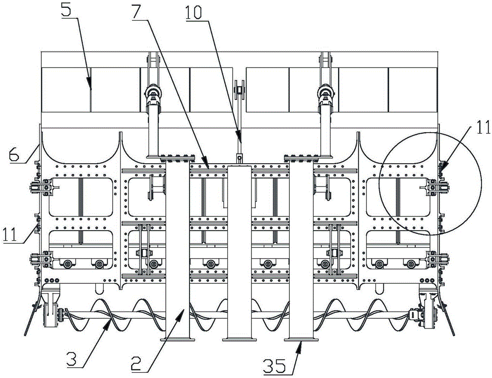
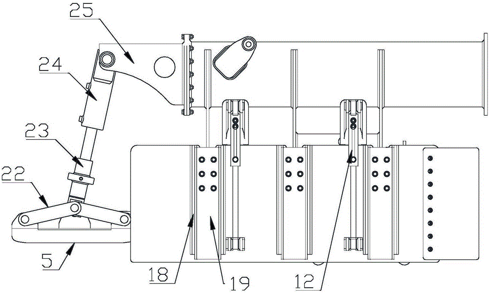
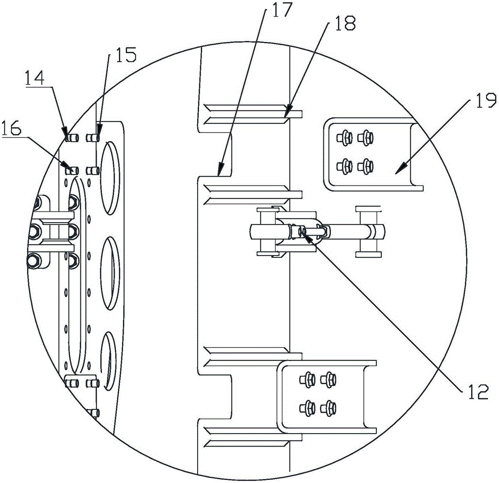
[0026] Such as Figure 1 to Figure 8 As shown in , a post-mounted slipform paver pavement slipform mold, which includes a beam frame 1, a rectangular connecting beam 2, a spiral distribution shaft 3, a vibrating rod 4, a wiper plate 5, and a side adjustment plate 6, wherein the beam frame 1 includes a square main beam frame 7, a rectangular connecting beam 2 is fixed on the top of the main beam frame 7, and connecting ports 35 are welded on the front and rear ends of the rectangular connecting beam 2 for connecting with the main frame, and fixed at the bottom of the front end of the main beam frame 7 A spiral distribution shaft 3 is provided, and a vibrating rod cylinder 8 with a piston rod protruding downwards is vertically fixed on both sides of the center of the main beam frame 7 behind the spiral distributing shaft 3. Both sides of the upper end surface of the fixed beam 9 are hinged, and the vibrating rod fixed beam 9 is arranged on the bottom of the main beam frame 7 axi...

Embodiment 2

[0032] Such as Figure 6 to Figure 12 As shown in , a post-mounted slipform paver pavement slipform mold, which includes a beam frame 1, a rectangular connecting beam 2, a spiral distribution shaft 3, a vibrating rod 4, a wiper plate 5, and a side adjustment plate 6, wherein the beam frame 1 includes a square main beam frame 7, a rectangular connecting beam 2 is fixed on the top of the main beam frame 7, and connecting ports 35 are welded on the front and rear ends of the rectangular connecting beam 2 for connecting with the main frame, and fixed at the bottom of the front end of the main beam frame 7 A spiral distribution shaft 3 is provided, and a vibrating rod cylinder 8 with a piston rod protruding downwards is vertically fixed on both sides of the center of the main beam frame 7 behind the spiral distributing shaft 3. Both sides of the upper end surface of the fixed beam 9 are hinged, and the vibrating rod fixed beam 9 is arranged on the bottom of the main beam frame 7 ax...


PUM


Abstract

The invention discloses a rear-mounted sliding formwork paver road surface sliding formwork mold which comprises a beam frame, a rectangular connecting beam, a screw distribution shaft, a vibration stick, a plastering plate and side adjusting plates. The beam frame comprises a main square beam frame body. A rectangular connecting beam is fixedly arranged above the main beam frame body. Connectors are welded to the front end face and the rear end face of the rectangular connecting beam respectively. The two sides of the center of the main beam frame body behind the screw distribution shaft are each fixedly and vertically provided with a vibration stick oil cylinder with a piston rod stretching downwards. The top ends of the piston rods of the vibration stick oil cylinders are hinged to the two sides of the upper end face of a vibration stick fixing beam. The vibration stick fixing beam and the screw distribution shaft are arranged at the bottom of the main beam frame body in an axially-parallel mode. The plastering plate is arranged at the rear end of the main beam frame body. A plastering plate horizontal driving device is horizontally and fixedly arranged in the middle of the bottom of the main beam frame. Positioning devices are perpendicularly and fixedly arranged on the two sides of the main beam frame body. The side adjusting plates which vertically slide are arranged on the positioning devices.

Description

Technical field: [0001] The invention relates to construction equipment for a slip-form paver, in particular to a rear-mounted slip-form paver pavement slip-form mold. Background technique: [0002] Slip form construction is a construction technology of cast-in-place concrete engineering using slip form molds. Compared with conventional construction methods, this construction technology has fast construction speed and high degree of mechanization. At present, there are two main methods, one is light The mechanical configuration method, that is, the main work is completed by machinery, and the auxiliary work is completed by manual labor and small machines. Large-scale bracket type multi-saw sawing machine, equipped with a large enough concrete mixing building in the background, to achieve full mechanization and rapid construction. The sliding form molds configured by these two methods of equipment are all placed in the middle part of the inner side of the equipment track, tha...

Claims


Application Information

Patent Timeline
IPC IPC(8): E01C19/48
Inventor 陈建军
Owner 山东万利精密机械制造有限公司
Learn More