
Miniature cylindrical launched unmanned plane and launcher

A launching device and unmanned aerial vehicle technology, applied in the direction of launch/drag transmission, motor vehicles, aircraft control, etc., can solve the problems of increasing the difficulty of launching boxes/canisters, fast flight speed, danger, etc., to improve reconnaissance and combat capabilities , convenient transportation and storage, and high space utilization

Active Publication Date: 2015-11-11
NO 27 RES INST CHINA ELECTRONICS TECH GRP
View PDF6 Cites 34 Cited by
  • Summary
  • Abstract
  • Description
  • Claims
  • Application Information

AI Technical Summary

Problems solved by technology

Compared with the barrel-type launch of the UAV, the box-type launch technology has the following disadvantages: First, because the thermal launch is boosted by the rocket in the launch box, it needs to be analyzed according to the temperature field and pressure field of the gas flow, and needs to be analyzed. Install a gas discharge device that can withstand multiple high-temperature and high-speed gas flows; secondly, the discharge mechanism of the box-type launch technology is usually relatively complicated, and the storage, transportation and use of pyrotechnic products designed by the box-type launch technology have certain dangers At the same time, the sound, light, smoke and other characteristics during the launch process make the launch site easy to leak
Although the modified wing can change the position and area of ​​the wing to meet the requirements of flight performance at different stages, correspondingly, the modified wing must add rotating shafts, connecting rods, steering gear and power devices to the fuselage and wings. , which increases the difficulty of loading into the launch box / tube, and makes the mission load factor smaller, and cannot carry some reconnaissance equipment on board
Moreover, in order to achieve different wing combinations, the variant wing often has a small wing area and a fast flight speed, which is not conducive to detection and positioning.

Method used


Image

  • Miniature cylindrical launched unmanned plane and launcher
  • Miniature cylindrical launched unmanned plane and launcher
  • Miniature cylindrical launched unmanned plane and launcher

Examples


Embodiment Construction

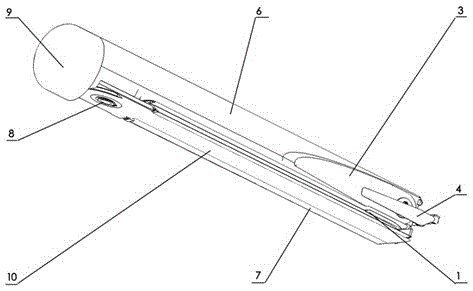
[0028] Such as figure 1 As shown, a small-sized barrel-type launching UAV and a launching device include a folding-wing UAV body, a barrel-type launching device for placing and launching a folding-wing UAV body 6 and a folding-wing UAV body. The wings of the wing and the locking device for launching the wing of the unmanned aerial vehicle after launch; the body of the folding wing unmanned aerial vehicle consists of a nose 9, a fuselage 6, a pair of rear wings 1, a pair of main wings 10, Composed of a pair of vertical tails 3 and a pair of folding propellers 4; Figure 4 As shown, the machine head 9 is mechanically connected to the machine body flange 16 through the machine head flange 15 and the machine body flange 16, and the three threaded holes on the machine body flange correspond to the waist holes of the machine head flange, which can be fine-tuned according to the situation. The main wing, the rear wing and the vertical tail of the drone are all connected with the fu...


PUM


Abstract

The invention discloses a miniature cylindrical launched unmanned plane and a launcher. An unmanned plane is provided with folding wings and in a storage state, the wings are folded below the plane body so that a space utilization rate is high and transport and storage are convenient. The miniature cylindrical launched unmanned plane can be arranged in a launch canister with the corresponding caliber, can be carried conveniently and is suitable for individual equipment. The miniature cylindrical launched unmanned plane can be deployed conveniently and can be immediately used in an individual load state. The miniature cylindrical launched unmanned plane is free of a launch place and a runway, can be used in a plain, an abrupt slope or rough topography such as a mountainous region, has small topography dependence, can be operated simply and can realize one-click launch after communication between the unmanned plane launcher and a ground station.

Description

technical field [0001] The invention relates to the field of small unmanned aerial vehicles and launching, in particular to a small-sized barrel-type launching unmanned aerial vehicle and a launching device. Background technique [0002] The launch phase of UAVs is often considered to be one of the most difficult and critical stages in the combat use of UAVs. The launch phase of UAVs directly affects the maneuverability, regional adaptability, repeatability, and Combat technical indicators and requirements such as usability and survivability. [0003] In order to meet the needs of front-line reconnaissance, the concept of barrel-type launching UAV was first proposed, that is, the UAV with a foldable and unfolding mechanism is loaded into the launch tube of the corresponding caliber by folding the wings. The hydraulic / pneumatic energy is converted into mechanical kinetic energy, so that the UAV can be accelerated to a safe take-off speed in a certain length of launch tube. A...

Claims


Application Information

Patent Timeline
IPC IPC(8): B64C39/00B64C1/30B64F1/06
Inventor 翟彬马建超郭彬新马云飞薛明旭胡溥瑞杨磊松吴长胜张微吉海明焦永磊邹时平宋玙薇
Owner NO 27 RES INST CHINA ELECTRONICS TECH GRP
Learn More