
Battery thermal management system

A thermal system, battery technology, applied in the direction of battery, secondary battery, battery temperature control, etc., can solve the problem of reducing vehicle occupant vehicle space and so on

Inactive Publication Date: 2015-11-11
FORD GLOBAL TECH LLC
View PDF6 Cites 0 Cited by
  • Summary
  • Abstract
  • Description
  • Claims
  • Application Information

AI Technical Summary

Problems solved by technology

[0003] However, placing the battery adjacent to the passenger compartment of the vehicle reduces the vehicle space available to the vehicle occupants

Method used


Image

  • Battery thermal management system
  • Battery thermal management system

Examples


Embodiment Construction

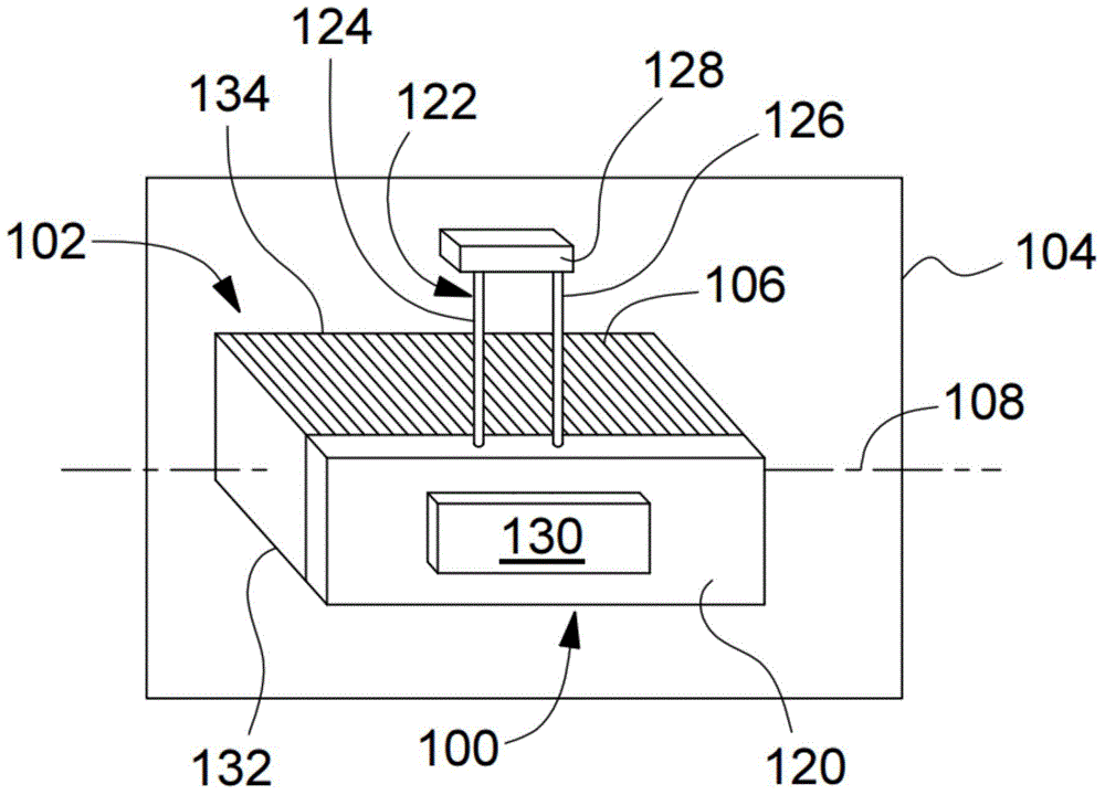
[0039] figure 1 with figure 2 A battery thermal management system 100 for a battery 102 on a motor vehicle 104 is schematically illustrated.

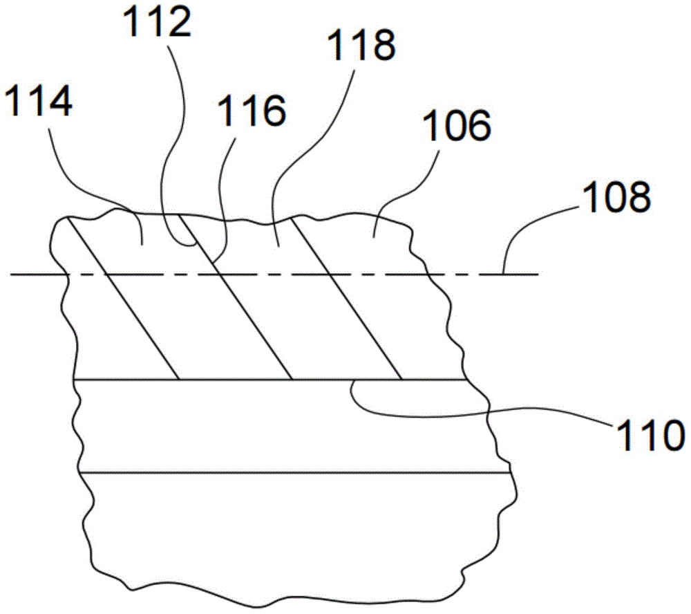
[0040] The battery 102 is composed of a plurality of individual cells 106 arranged along an axis 108 . End face 110 is parallel to axis 108 . The first side 112 of the first unit 114 is in contact with the second side 116 of the adjacent second unit 118 . Both first and second sides 112 and 116 are perpendicular to end face 110 . As used herein, a "side" is a face of a unit that faces toward and is adjacent to (and possibly in contact with) a side of an adjacent unit. Then, in this particular assembly of adjacent units, the "end face" is not facing the side of the adjacent unit.

[0041] The first heat exchanger 120 contacts and spans the end face 110 . Conduit 122 fluidly communicates first heat exchanger 120 and second heat exchanger 128 to transfer heat between first heat exchanger 120 and second heat exchanger 128 . The cond...


PUM


Abstract

A battery is assembled from cells arranged along an axis. The cells have end faces parallel to the line and first and second sides perpendicular to the faces. The first side of a first cell contacts the second side of a second cell. A sealed piping circuit includes a first heat exchanger in contact with, and spanning, the end faces and a second heat exchanger in fluid communication with the first heat exchanger for heat transfer between the heat exchangers.

Description

Background technique [0001] The present invention relates to motor vehicle batteries, and in particular to a management system for the thermal state of the battery. [0002] A hybrid electric powertrain of a motor vehicle may include a battery composed of multiple cells. Normally, batteries are kept within an optimal temperature range to operate efficiently. For example, by placing the battery adjacent to the passenger compartment of the vehicle, the battery can be kept in an optimal temperature range. [0003] However, placing the battery adjacent to the passenger compartment of the vehicle reduces the vehicle space available to the vehicle occupants. Contents of the invention [0004] One embodiment proposes a battery thermal system. A battery has cells arranged along an axis with end faces of the cells parallel to the axis. The first and second heat exchangers are in a sealed pipe loop. The first heat exchanger contacts and spans the end faces. A second heat exchang...

Claims


Application Information

Patent Timeline
Patent Type & Authority Applications(China)
IPC IPC(8): B60L11/18H01M10/625H01M10/6556
CPCH01M10/6552H01M10/613H01M10/625H01M10/63H01M10/6551H01M2220/20H01M10/615H01M10/6556H01M10/6568Y02E60/10
Inventor 巴斯卡拉·波达卡亚拉布鲁斯·C·布莱克默周世光雷蒙德·C·西恰克
Owner FORD GLOBAL TECH LLC
Learn More