
Device used for machining end face cam

An end-face cam and worm gear shaft technology, which is applied to feeding devices, metal processing equipment, metal processing machinery parts, etc., can solve the problems of affecting end-face cam processing, high cost, and complex three-jaw chuck structure.

Inactive Publication Date: 2015-11-11
重庆市合川区均恒金属加工厂
View PDF5 Cites 1 Cited by
  • Summary
  • Abstract
  • Description
  • Claims
  • Application Information

AI Technical Summary

Problems solved by technology

Existing devices for machining end cam curves usually use a three-jaw chuck for positioning and clamping. The three-jaw chuck has a complex structure and high cost; However, if the workbench has a position deviation during long-term work, the feed is not in place or the feed is too much, it cannot be adjusted independently, which will affect the processing of the end cam

Method used


Image

  • Device used for machining end face cam

Examples


Embodiment Construction

[0011] The present invention will be described in further detail below by means of specific embodiments:

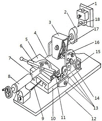
[0012] The reference signs in the drawings of the description include: tool rest 1, cam blank 2, workpiece headstock 3, longitudinal slide 4, transverse slide 5, inclined ruler 6, screw 7, base 8, return spring 9, guide rail 10, transverse Screw mandrel 11, base 12, driven gear set 13, driving gear 14, worm shaft 15, headstock support 16, worm wheel 17, cutter 18.

[0013] The embodiment is basically as attached figure 1 Shown: This embodiment is used to process the device of the end face cam, including the worm shaft, the worm shaft is driven by power, the worm shaft is provided with a runner, and the runner is provided with a columnar handle. Turn the handle to drive the worm shaft to rotate.

[0014] The worm shaft passes directly through the headstock, and the worm shaft is provided with a worm on the inner side of the headstock support, and a worm gear meshes with ...


PUM


Abstract

The invention discloses a device used for machining an end face cam. By means of the device, the position of a working table can be adjusted. The device comprises a worm shaft driven through power. The worm shaft drives a worm wheel shaft to rotate through a worm and a worm wheel. The worm wheel shaft is sued for driving the end face cam to rotate. A driving gear is arranged on the worm shaft and drives a transverse lead screw to rotate through driven gears which are sequentially meshed with one another. The transverse lead screw is connected with a nut in a threaded manner. The nut is fixed to the bottom of a transverse slide plate which is guided in the transverse direction through a slide block on the upper portion of a vertical slide plate. The vertical slide plate is arranged on a vertical guide rail. A limiting block abutting against the side face of a longitudinal slide plate is fixed to the end of the transverse lead screw. A guide column is fixed to the upper portion of the transverse slide plate and located in an arc-shaped groove of an inclined ruler. The arc top of the arc-shaped groove faces one side of the end face cam. The inclined ruler is located on the upper portion of the transverse slide plate. The side, away from the end face cam, of the inclined ruler is hinged to one end of a threaded rod which is connected to a horizontal base in a threaded manner. A handle is arranged at the other end of the threaded rod.

Description

technical field [0001] The invention relates to a device for machining end cams. Background technique [0002] Cam is a common part of various mechanical equipment. There are many types of cams, disc cams and cylindrical cams are commonly used. The end cam is a kind of cylindrical cam. The cam whose profile curve is located at the end of the cylinder and rotates around its axis is called an end cam. Existing devices for machining end cam curves usually use a three-jaw chuck for positioning and clamping. The three-jaw chuck has a complex structure and high cost; However, if the worktable has a position deviation during long-term work, the feed is not in place or the feed is excessive, it cannot be adjusted independently, which will affect the processing of the end cam. Contents of the invention [0003] The present invention intends to provide a device for processing end face cams which can adjust the position of the workbench. [0004] The device for processing the end ...

Claims


Application Information

Patent Timeline
Patent Type & Authority Applications(China)
IPC IPC(8): B23Q5/22
CPCB23Q5/22
Inventor 王树尧
Owner 重庆市合川区均恒金属加工厂
Learn More