
A hole punching mechanism for a transplanting machine

A technology of transplanting machine and sliding rail, applied in the directions of planting method, excavation/covering of trenches, application, etc., can solve the problems of tearing the film, affecting the transplanting effect, easy clay, etc., to achieve the effect of improving the effect.

Active Publication Date: 2017-03-22
张培坤
View PDF6 Cites 0 Cited by
  • Summary
  • Abstract
  • Description
  • Claims
  • Application Information

AI Technical Summary

Problems solved by technology

Because such a deep hole has a certain effect of keeping warm and moisturizing, reducing the time of direct sunlight, it can also avoid the seedlings in the hole from being affected by freezing damage and spring drought in the early stage of transplanting, and greatly improve the survival rate of transplanting. Artificial planting is inefficient, labor-intensive and time-consuming, and delays the best planting time. In the current situation where labor costs are getting higher and higher, artificial planting can no longer meet the needs of large-scale planting. For this, the patent application number is 201420241441.6 The literature provides a transplanting machine, which can be used for opening holes and planting seedlings in the field. However, since the hole opening knife used for opening holes moves with the transplanting machine, there is still a small relative movement between the ridge and the ground. The outer side of the upper part of the soil is easy to clay, and it is easy to cause the hole cutter to tear the film when the film is spread on the field, which seriously affects the transplanting effect

Method used


Image

  • A hole punching mechanism for a transplanting machine
  • A hole punching mechanism for a transplanting machine
  • A hole punching mechanism for a transplanting machine

Examples


Embodiment 1

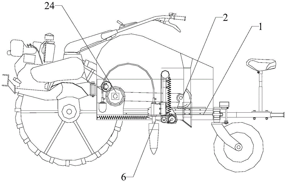
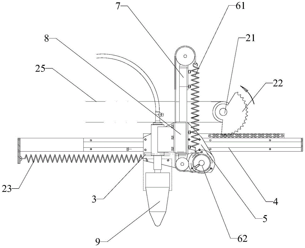
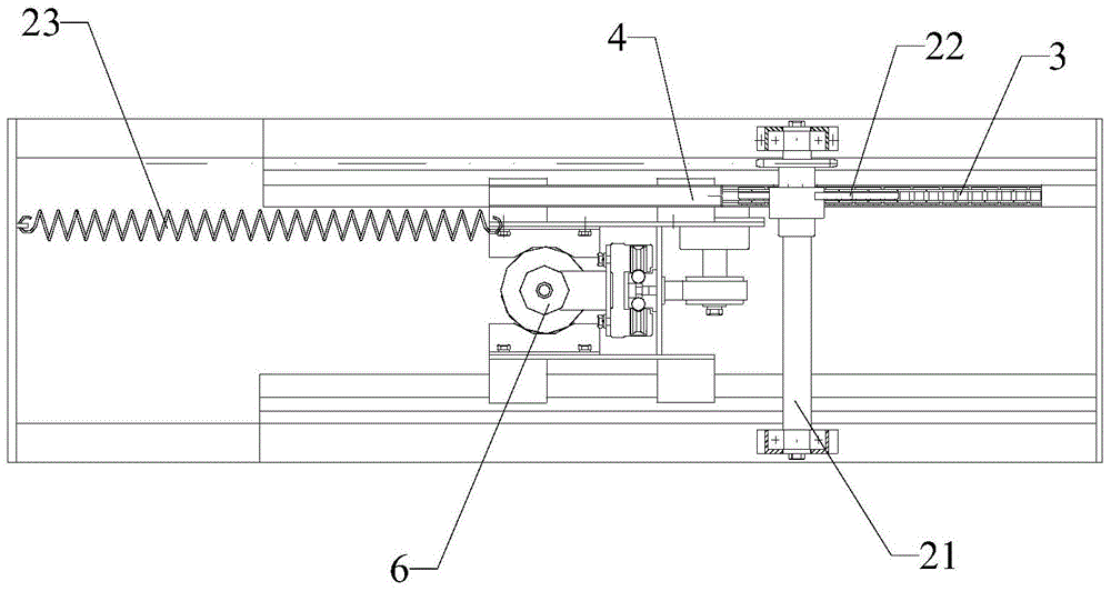
[0043] Please refer to Figure 1 to Figure 5 Shown, embodiment one of the present invention is:

[0044] A hole punching mechanism for a transplanting machine, comprising a bracket 1, a driving device 2, a first rack 3, a first slide rail 4, a first slider 5, a hole punching device 6, a reducer 24 and a chain belt 25; The first sliding rail 4 is horizontally fixed on the bracket 1, the first sliding block 5 cooperates with the first sliding rail 4, the hole punching device 6 is fixed on the first sliding block 5, and the driving device 2 drives the first The slider 5 and the punching device 6 move horizontally on the first slide rail 4; the first rack 3 is fixed on the support 1, and the punching device 6 is provided with a drive shaft. The rack 3 drives the driving shaft to rotate. The driving device 2 includes a rotating shaft 21, a sector gear 22 and a first spring 23. Two racks 26, the rotating shaft 21 is rotatably installed on the bracket 1, the sector gear 22 is mount...


PUM


Abstract

The invention relates to the field of seedling transplantation and aims at providing a hole excavating mechanism of a transplanting machine. The hole excavating mechanism of the transplanting machine comprises a support, a driving device, a first rack, a first slide rail, a first slider and a hole excavating device. The first slide rail is horizontally fixed to the support. The first slider is matched with the first slide rail. The hole excavating device is fixed to the first slider. The driving device drives the first slider and the hole excavating device to horizontally move on the first slide rail. The hole excavating mechanism of the transplanting machine has the advantages that the hole excavating device moves backwards in the hole excavating process so that the forward movement speed of the transplanting machine can be counteracted, a hole excavating cone can be static relative to a ground ridge when moving up and down for hole excavation, it is avoided that the hole excavating device breaks a thin film, the hole excavating and transplanting effects are improved, the hole excavating device is driven through the first rack fixed to the support, the displacement of the hole excavating device and the hole excavating process are made to be performed at the same time all the time, and synchronous movement is achieved.

Description

technical field [0001] The invention relates to the field of seedling transplanting, in particular to a hole punching mechanism of a transplanting machine. Background technique [0002] In most areas of southern and western my country, two types of crop rotations are generally adopted for the planting of commercial crops, usually tobacco leaves, peppers, rice, and corn. The planted seedlings will be affected and restricted by the late spring cold current and spring drought. With the development of agricultural planting technology, many areas have begun to promote a pit-type seedling transplanting method. It is to manually use a conical wooden stick to make a hole with a diameter of 8 cm and a depth of 18-20 cm on the ridge. hole, put the crop seedlings into the hole, and pour an appropriate amount of root-fixing water on it. Because such a deep hole has a certain effect of keeping warm and moisturizing, reducing the time of direct sunlight, it can also avoid the seedlings i...

Claims


Application Information

Patent Timeline
Patent Type & Authority Patents(China)
IPC IPC(8): A01C5/04
Inventor 张培坤王又沐张心伟
Owner 张培坤
Learn More