Photographing method with projection light source and photographing device

A camera device and light source technology, which is applied in projection devices, optics, image communication, etc., can solve the problems of wasting the photographer's time and the uncertainty of whether the captured image is clear, and achieves the effect of improving accuracy

Inactive Publication Date: 2015-11-04
LOTES SHENZHEN
View PDF7 Cites 16 Cited by
  • Summary
  • Abstract
  • Description
  • Claims
  • Application Information

AI Technical Summary

Problems solved by technology
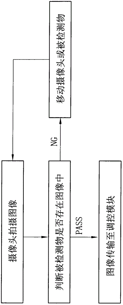
In addition, most of the imaging elements cannot ensure that a clear image of the object to be detected can be obtained in one shot. The photographer needs to adjust the color or brightness of the light source to shoot the object to be detected. This process will waste a lot of time for the photographer; Whether the captured image is clear or not depends on the photographer’s visual inspection of the captured image. If the photographer thinks the image is clear, the captured image will be output; Until the photographer thinks the captured image is clear, this process is mainly determined by the photographer's own technical experience, so there will be great uncertainty about whether the captured image is clear

Method used


Image

  • Photographing method with projection light source and photographing device
  • Photographing method with projection light source and photographing device
  • Photographing method with projection light source and photographing device

Examples


Embodiment Construction

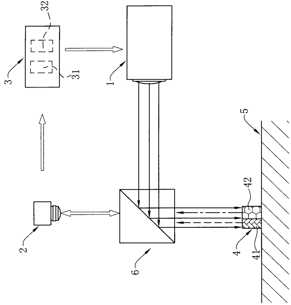
[0052] In order to facilitate a better understanding of the purpose, structure, features, and effects of the present invention, the present invention will now be further described in conjunction with the accompanying drawings and specific embodiments.

[0053] see figure 1 As shown, the imaging device of the present invention includes: a projection light source 1, which can emit illumination lights of various colors and brightnesses, and the lights of various colors and brightnesses emitted by the projection light source 1 can be adjusted and controlled The irradiation light emitted by the projection light source 1 is correspondingly projected on a detected object 4; a camera 2 is used to photograph the irradiated detected object 4 to form an image (not shown); an image analysis and processing module 31, The image analysis processing module 31 is used to receive the captured image and analyze the image; the camera 2 transmits the captured image to the The image analysis and p...


PUM


Abstract

The invention discloses a camera shooting method achieved through camera shooting elements. The camera shooting elements include a three-primary-color projector, a camera and a regulating module, wherein the three-primary-color projector can emit illumination light of various colors and various kinds of brightness, and the illumination light emitted from the three-primary-color projector is shot on a detected object; the camera is used for shooting the detected object to form an image; the regulating module is used for analyzing the image and regulating the color or the brightness of the illumination light emitted from the three-primary-color projector to carry out light compensation on a local area of the detected object. The image is transmitted to the regulating module, the regulating module presets a threshold value of a grey value of a graphic primitive of the image, the grey value of the graphic primitive in the image of the detected object and the threshold value are compared and analyzed, the regulating module regulates a light-emitting area of a corresponding block in the three-primary-color projector for the local area where the grey value of the image of the detected object is not within the range of the threshold value, and accordingly the clear image of the detected object is shot by means of matching of the method and the camera.

Description

【Technical field】 [0001] The invention relates to an imaging method with a projection light source and an imaging device thereof, in particular to an imaging method and an imaging device used in a visual detection processing system. 【Background technique】 [0002] The visual detection processing system mainly includes visual detection processing software and camera components. Its main function is to obtain images by shooting the detected object through the camera components, and then extract the dimensions, scratches, characters, etc. from the captured images through the visual detection processing software. According to the various information obtained, various operations such as detection, measurement, and identification are performed on the detected object. In this process, it is particularly important for the visual inspection processing software to accurately obtain various information from the image. In order to accurately obtain various information from the image, it...

Claims


Application Information

Patent Timeline
Patent Type & Authority Applications(China)
IPC IPC(8): H04N5/235G03B21/20G06V10/141G06V10/147G06V10/25G06V10/50G06V10/88
CPCG06V10/141G06V10/147G06V10/25G06V10/50G06V10/88G06V2201/06H04N23/56H04N23/74
Inventor 廖德林林文杰
Owner LOTES SHENZHEN
Why Eureka
Try Eureka