
Electroencephalogram identification method based on different expression drivers

A technology of EEG signal and identification method, applied in the input/output of user/computer interaction, computer parts, graphic reading, etc., can solve the problems of light intensity stimulation, reducing experimental accuracy, easy to produce fatigue and so on

Active Publication Date: 2015-11-04
XI AN JIAOTONG UNIV
View PDF6 Cites 21 Cited by
  • Summary
  • Abstract
  • Description
  • Claims
  • Application Information

AI Technical Summary

Problems solved by technology

Although the evoked EEG signal has the characteristics of high resolution and strong anti-interference ability, its disadvantage is that it relies too much on the inducing source, and at the same time, it is easy to cause fatigue and even induce epilepsy after a long time inducing experiment.
Tsinghua University realized the pouring process of the four-free prosthesis through the steady-state visually induced brain-computer interface system, but the long-term light intensity stimulation will reduce the accuracy of the experiment
[0004] At present, domestic scholars still mainly focus on the research of motor imagery, motion recognition, and steady-state visually evoked brain-computer interface systems. However, research on EEG signals driven by facial expressions has not yet seen mature technical reports on related topics.

Method used


Image

  • Electroencephalogram identification method based on different expression drivers
  • Electroencephalogram identification method based on different expression drivers
  • Electroencephalogram identification method based on different expression drivers

Examples


Embodiment Construction

[0052] The present invention will be described in further detail below in conjunction with the accompanying drawings and embodiments.

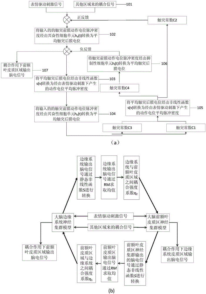
[0053] refer to figure 1 , a modeling method based on different facial expressions driving EEG signal generation mechanism, according to physiological and anatomical knowledge, the areas of the cerebral cortex that are driven by expressions are concentrated in the prefrontal cortex area S1 and the limbic system area S2. The multi-dynamic characteristics of the cluster model the two regions S1 and S2, which specifically includes the following steps:

[0054] Step 1. According to 101, respectively establish two independent sub-regions of the prefrontal cortex area S1 and the limbic system area S2 EEG signal generation models. The input signals of S1 area and S2 area are other cerebral cortex EEG signals and the average pulse density of synaptic action potential generated by expression drive.

[0055] Step 2 According to 102, set each excitator...


PUM


Abstract

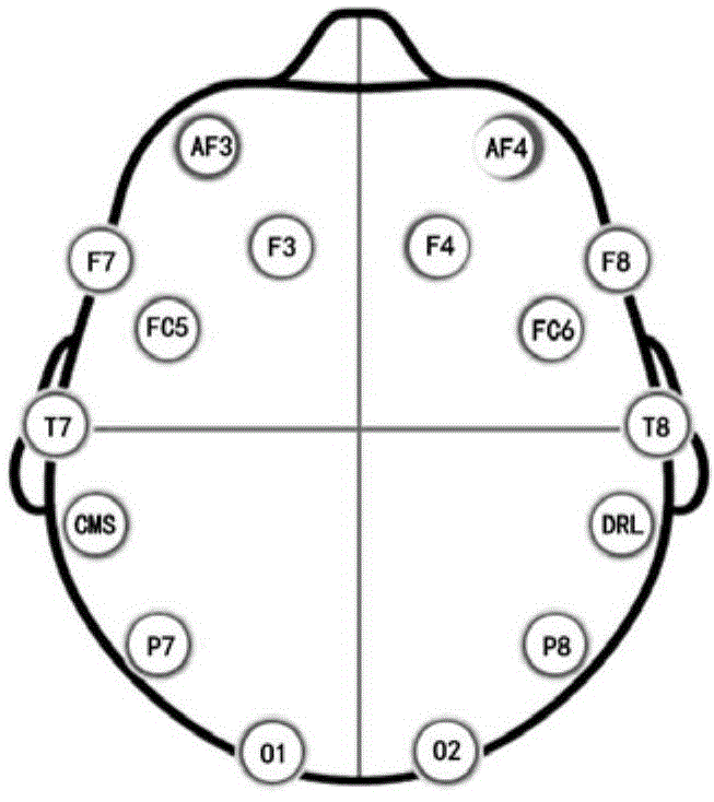
The present invention discloses an electroencephalogram identification method based on different expression drivers, which is characterized in that based on cerebrophysiology knowledge, firstly, electroencephalograms generated by different face expression drivers are subjected to modeling simulation analysis; and on the basis, signal features of an Alpha wave band and a theta wave band in the electroencephalograms, which are generated on the basis of positions of four measurement points of FC5, FC6, F7 and F8 of the brain in the face expression driving process, are used as the basis of electroencephalogram classification identification for driving control of the electroencephalograms.

Description

technical field [0001] The invention relates to brain-computer interface technology, in particular to a method for researching brain electrical signals driven by facial expressions. Background technique [0002] The latest development of brain-computer interface technology has developed from a simple brain-computer interface to a brain-electromechanical device, that is, by extracting the EEG signals generated by the human brain cortex, inferring the thinking activities of the brain and translating them into corresponding commands to control peripheral electromechanical devices, such as disabled wheelchairs, smart prosthetic hands or exoskeleton robots, etc., in order to realize the mind control of these peripheral devices. With the development of biomechatronics technology in recent years, more and more characteristic EEG signals have been applied in the research of brain-computer interface paradigm. According to different control sources, BCI systems are mainly divided int...

Claims


Application Information

Patent Timeline
Patent Type & Authority Applications(China)
IPC IPC(8): G06F3/01
Inventor 张小栋李睿陈江城刘畅郭晋赖知法尹贵
Owner XI AN JIAOTONG UNIV
Learn More