Multi-pass shell-and-tube flooded heat exchanger

A flooded, heat exchanger technology, applied in indirect heat exchangers, heat exchanger types, refrigeration and liquefaction, etc., can solve the problem of poor stability of the oil return system, large increase in unit cost, and high cost Not inferior to other problems, to achieve the effect of easy anti-corrosion treatment, simple structure and low cost

Active Publication Date: 2015-11-04
ZHEJIANG QINGFENG REFRIGERATION EQUIP MFG
View PDF6 Cites 6 Cited by
  • Summary
  • Abstract
  • Description
  • Claims
  • Application Information

AI Technical Summary

Problems solved by technology

However, the use of this method for scroll chillers will result in high cost and difficulty in oil return. It is necessary to install secondary oil separation and an ejector oil return system.
In this way, although the energy efficiency of the small flooded unit is slightly improved, the cost of the unit is increased by a large proportion, and the economy is not good.
At the same time, oil return and ejection will cause part of the refrigerant to return directly to the compressor without heat exchange, resulting in a large loss of cooling capacity, and the energy efficiency is very limited compared with the dry-type unit.
At the same time, the stability of the oil return system is not very good.
Because the traditional flooded evaporator has a large shell, the 50% liquid charge of the evaporator makes the cooling charge large, which is 60% more than the dry evaporator, and the cost remains high

Method used


Image

  • Multi-pass shell-and-tube flooded heat exchanger
  • Multi-pass shell-and-tube flooded heat exchanger
  • Multi-pass shell-and-tube flooded heat exchanger

Examples


Embodiment Construction

[0017] A detailed description will be given below of specific embodiments of the present invention according to the accompanying drawings.

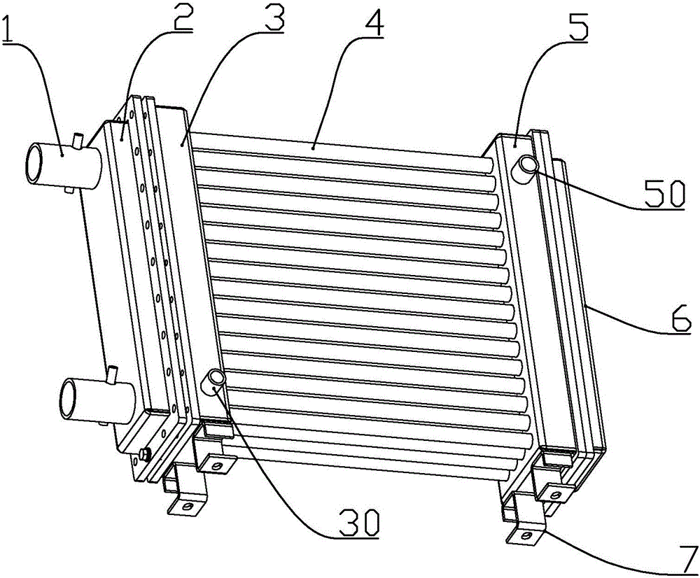
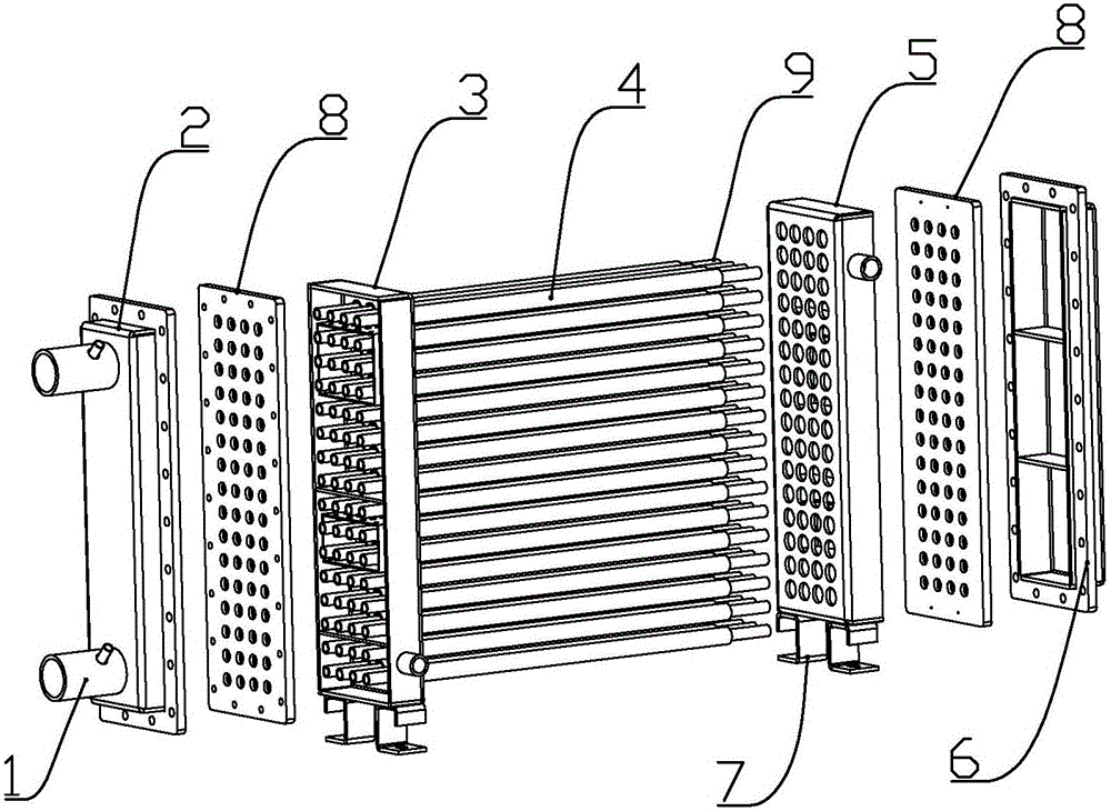
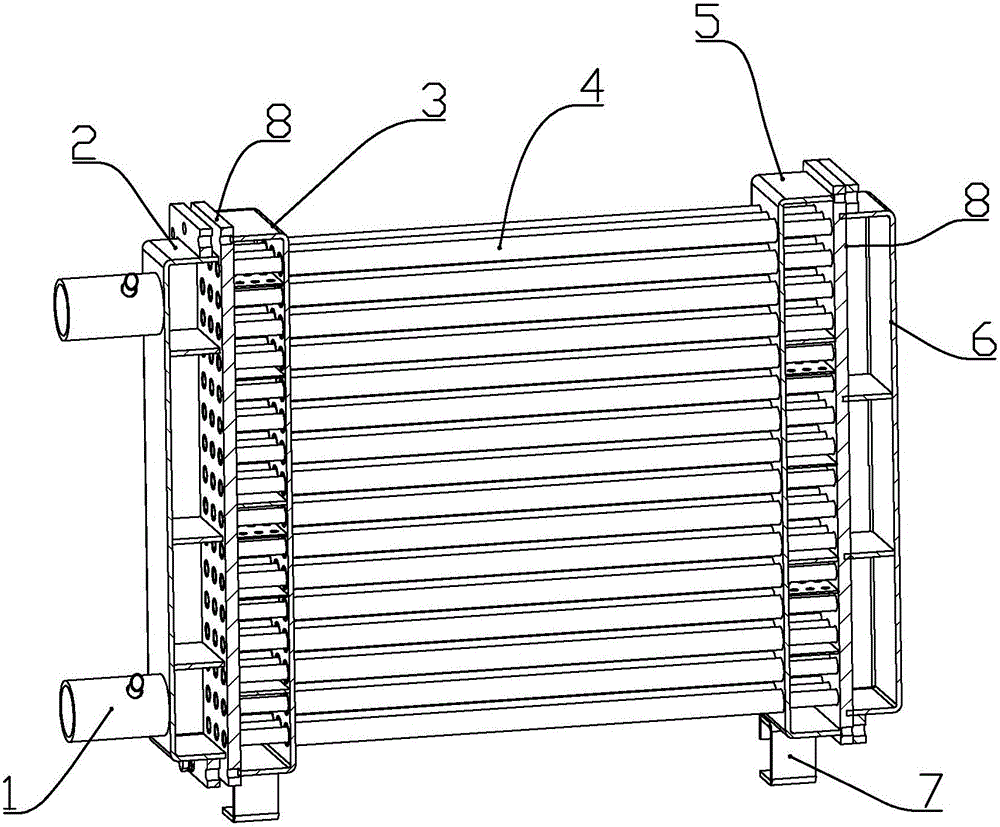
[0018] according to Figure 1 to Figure 5 As shown, the present embodiment is a multi-shell tube flooded heat exchanger, including a plurality of shell tubes 4 distributed in an array, a plurality of heat exchange tubes 9 passing through each shell tube, and the two ends of each shell tube respectively A first outer tube box 3 and a second outer tube box 5 are connected and communicated, and two tube sheets respectively connected to both ends of each heat exchange tube and connected to the outside of the first outer tube box and the second outer tube box 8, and a first inner tube box 2 and a second inner tube box 6 respectively connected to the outside of the two tube sheets; the two ends of the shell tube are sealed with the first outer tube box and the second outer tube box respectively Insertion, the two ends of the heat exchange tube...


PUM


Abstract

The invention discloses a multi-pass shell-and-tube flooded heat exchanger. The multi-pass shell-and-tube flooded heat exchanger comprises a plurality of outer shell tubes in array distribution, a plurality of heat exchange tubes penetrating the outer shell tubes, a first outer tube box, a second outer tube box, two tube plates, a first inner tube box and a second inner tube box, wherein the first outer tube box and the second outer tube box are respectively connected with the two ends of each outer shell tubes and are mutually communicated; the two tube plates are respectively connected with the two ends of each heat exchange tube, as well as the outer sides of the first outer tube box and the second outer tube box; the first inner tube box and the second inner tube box are respectively connected to the outer sides of the two tube plates; and the lower part of the first outer tube box is connected with a refrigerant inlet adapter, and the upper part of the second outer tube box is connected with a refrigerant outlet adapter. The multi-pass shell-and-tube flooded heat exchanger realizes passing of a refrigerant on both the shell side and the tube side, and adopts the structure that the outer shell tubes sleeve the heat exchange tubes, so that the refrigerant filling amount is much less than that of a common flooded evaporator, and the oil return performance is good.

Description

technical field [0001] The invention belongs to the field of heat exchangers of refrigeration equipment, and in particular relates to a multi-shell tube flooded heat exchanger which can be used as a condenser or an evaporator. Background technique [0002] The existing technology adopts flooded evaporators with large shells and large spaces, which are generally used in larger cold and hot water units, such as screw chillers and centrifugal chillers, and generally used in smaller scroll chillers. Use dry evaporation, or directly borrow the design method of flooded evaporator for larger units. This method is generally adopted because it has the advantages of high energy efficiency, low cost, and relatively mature technology when used on larger units. However, using this method for scroll chillers will result in high cost and difficulty in oil return. It is necessary to install secondary oil separation and an ejector oil return system. In this way, although the energy...

Claims


Application Information

Patent Timeline
Patent Type & Authority Applications(China)
IPC IPC(8): F25B39/00F28D7/16
Inventor 陈光金袁杰金阿龙朱勇俊温素珍邱辉
Owner ZHEJIANG QINGFENG REFRIGERATION EQUIP MFG
Why Eureka
Try Eureka