Fully-automatic pipe end molding machine

A forming machine, fully automatic technology, applied in the field of fully automatic pipe end forming machine, can solve the problems of inconvenient fully automatic production and promotion, difficult processing and positioning, high production cost, etc., and achieve the effect of fast processing speed, convenient operation and high precision

Active Publication Date: 2015-11-04
HONORFAITH FURNITURE
View PDF13 Cites 0 Cited by
  • Summary
  • Abstract
  • Description
  • Claims
  • Application Information

AI Technical Summary

Problems solved by technology

The product structure processed in this way is single, and more practical pipe fittings often need to be pre-pressed and dotted on the nozzle, which makes subsequent processing and positioning difficult, and the number of processes increases and the production cost is high. Therefore, the existing single The equipment has shortcomings in the production of product parts with complex requirements, which is not convenient for the fully automated production and promotion of high-demand products

Method used


Image

  • Fully-automatic pipe end molding machine
  • Fully-automatic pipe end molding machine
  • Fully-automatic pipe end molding machine

Examples


Embodiment

[0023] Embodiment: A fully automatic pipe end forming machine

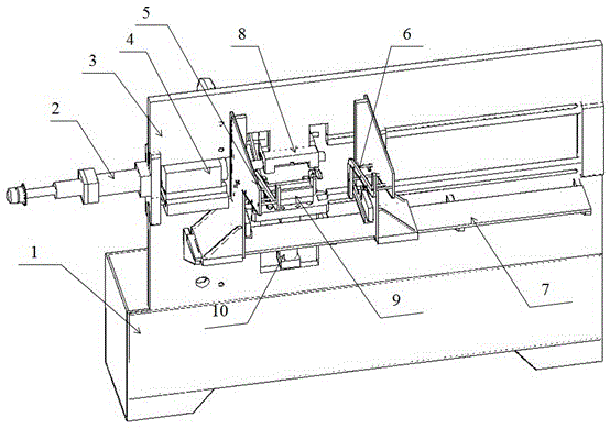
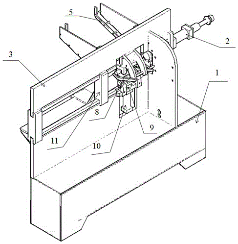
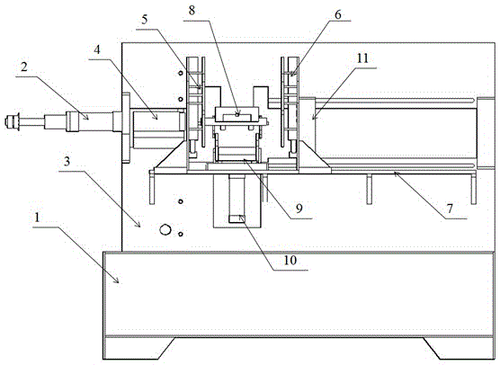
[0024] refer to Figure 1 to Figure 5 As shown, a fully automatic pipe end forming machine includes a stand 1, a fixed mount 3 is installed on the upper surface of the stand 1, and a retractable oil cylinder 2 is installed on the left end of the fixed mount 3, and the retracted oil cylinder 2 The right end of the feeder is connected with a shrinking die head 4, the front surface of the fixed frame 3 is provided with a fixed plate 7, the feeding device A5 and the feeding device B6 are installed on the fixed plate 7, and the right end of the feeding device B6 is connected with a Slider 11, said slider 11 is installed in the middle end of fixed frame 3, and upper mold clamp 8 is installed in the middle of feeding device A5 and feeding device B6, and the top is fixed on the fixed frame 3, and lower mold clamp 9 is installed in the said Just below the upper mold clamp 8, the bottom end is connected with the lower mold...


PUM


Abstract

The invention provides a fully-automatic pipe end molding machine which comprises a rack. The upper surface of the rack is provided with a fixing frame. A telescopic oil cylinder is arranged at the left end of the fixing frame. A telescopic die head is connected to the right end of the telescopic oil cylinder. The front surface of the fixing frame is provided with a fixing plate. A feeding device A and a feeding device B are arranged on the fixing plate. A sliding block is connected to the right end of the feeding device B. The sliding block is arranged in the middle end of the fixing frame. An upper die fixture is arranged between the feeding device A and the feeding device B. The top end of the upper die fixture is fixed to the fixing frame. A lower die fixture is arranged under the upper die fixture. The bottom end of the lower die fixture is connected with a lower die fixture thrusting cylinder. The fully-automatic pipe end molding machine is simple in structure, convenient to operate, capable of conducting feeding, material clamping and discharging automatically, high in machining speed, high in accuracy, capable of adjusting the distance between the feeding devices and meeting the feeding requirements of workpieces of different lengths and wide in adaptation.

Description

technical field [0001] The invention relates to the field of hardware processing equipment, in particular to a fully automatic pipe end forming machine. Background technique [0002] At present, the methods of pipe end forming are mainly divided into mechanical forming method, pipe end eccentric rotary forming and moldless forming, among which mechanical forming method is the most widely used. The mechanical forming method is all completed on the pipe end forming machine, which can process steel pipes, copper pipes or other metal pipes into different shapes according to product requirements. The common pipe end machines currently on the market usually include manual feeding, manual positioning and a pipe end forming mechanism, which is used to send pipe fittings into the forming mold for pressing. The product structure processed in this way is single, and more practical pipe fittings often need to be pre-pressed and dotted on the nozzle, which makes subsequent processing an...

Claims


Application Information

Patent Timeline
Patent Type & Authority Applications(China)
IPC IPC(8): B21D41/00
Inventor 曹作林
Owner HONORFAITH FURNITURE
Why Eureka
Try Eureka