Cable for charging facility of electric automobile

A technology for charging facilities and electric vehicles, applied in the direction of power cables, bendable cables, insulated cables, etc., can solve problems that have not been seen in technical revelations, and achieve the effects of avoiding damage, prolonging service life, and good pressure-bearing support Effect

Inactive Publication Date: 2015-10-28
3Q WIRE & CABLE
View PDF14 Cites 10 Cited by
  • Summary
  • Abstract
  • Description
  • Claims
  • Application Information

AI Technical Summary

Problems solved by technology

[0007] Undoubtedly, how to combine the advantages and disadvantages of the aforementioned two types of car charging cables to find a reasonable balance between rolling resistance, bending resistance, softness, lightness and low cost has become the focus of the industry. The technical problem expected to be solved, but there is no corresponding technical revelation in the Chinese and foreign patents and non-patent literature published so far

Method used


Image

  • Cable for charging facility of electric automobile
  • Cable for charging facility of electric automobile
  • Cable for charging facility of electric automobile

Examples


Embodiment 1

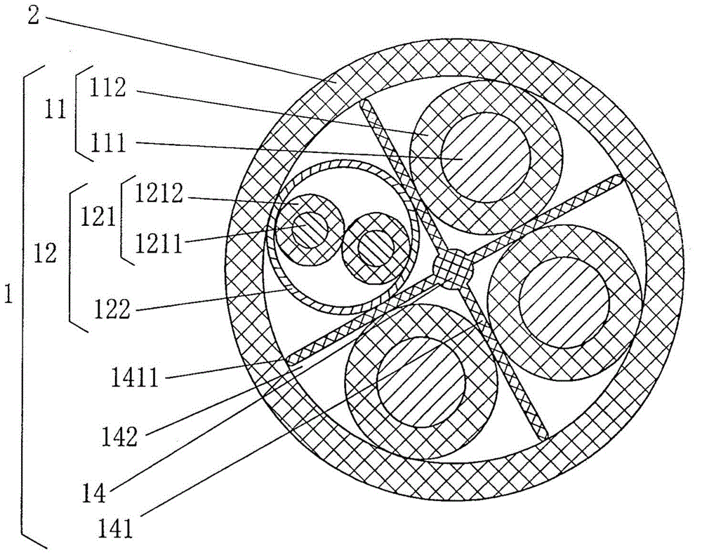
[0030] See figure 1 , figure 1 It is a cross-sectional schematic diagram of a cable used for electric vehicle charging facilities of the present invention, including a cable core 1 and a sheath layer 2 outside the cable core 1, and the cable core 1 includes a power line 11 and a signal line pair 12, and the power line 11 and the signal line The pairs 12 are located in the sheath layer 2 together, that is to say, the sheath layer 2 is extruded outside the power line 11 and the signal line pair 12 according to the usual sheath extrusion process in the production of electric wires and cables.

[0031]As the technical gist of the technical solution provided by the present invention: the aforementioned cable core 1 also includes a cable core supporting framework 14, which is located on the sheath layer 2 in the state accompanied by the aforementioned power line 11 and signal line pair 12 Inside, and the cable core support frame 14 has a group of support frame wings 141, the number...

Embodiment 2

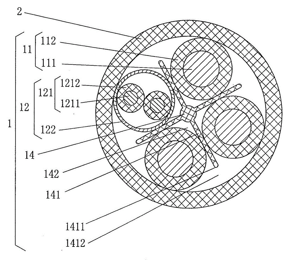
[0039] See figure 2 , in this embodiment, since the support skeleton wing space 1412 is maintained between the aforementioned support skeleton wing end face 1411 and the sheath layer 2, the support skeleton wing 141 is formed into a half-section support skeleton wing, thereby separating the wire into the cavity 142 constitutes a semi-closed cavity. All the other are the same as the description to embodiment 1.

Embodiment 3

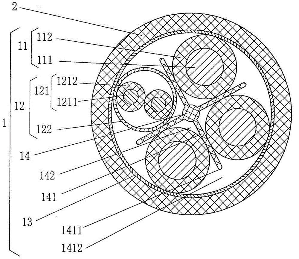
[0041] See image 3 A shielding layer 13 is added to the structural system of the aforementioned cable core 1, and the aforementioned power line 11, signal line pair 12 and cable core support frame 14 are located in the shielding layer 13 together. Due to the existence of the shielding layer 13, the aforementioned sheath Layer 2 is extruded outside the shielding layer 13. Since the supporting frame wing end face 1411 of a group of supporting frame wings 141 of the cable core supporting frame 14 and the shielding layer 13 maintain a supporting frame wing space 1412, thereby making a group of supporting frame wings 141 is formed as a half-section supporting frame wing, and the wire separation cavity 142 is formed as a semi-closed cavity, that is, a semi-closed cavity. The aforementioned shielding layer 13 is a wire braided shielding layer. What the applicant needs to explain is that if the aforementioned support frame wing space 1412 is abandoned and the support frame wing end ...


PUM

PropertyMeasurementUnit
thermal resistanceaaaaaaaaaa

Abstract

The invention provides a cable for a charging facility of an electric automobile, and belongs to the field of wires and cables. The cable comprises a cable core and a sheath layer positioned at the outside of the cable core, the cable core comprises power lines and a signal line pair, and the power lines and the signal line pair are positioned in the sheath layer. The cable is characterized in that the cable core also comprises a cable core support skeleton, the cable core support skeleton is positioned in the sheath layer with the power lines and the signal line pair, the cable core support skeleton is provided with a group of support skeleton wings, the group of support skeleton swings are distributed in a radiation manner in the direction of the cross section of the cable core support skeleton and extend towards the length direction of the cable core support skeleton, each two adjacent support skeleton wings form a totally-closed or semi-closed conducting wire separating chamber whose cross section is in a sector shape, and the power lines and the signal line pair, which are respectively separated by the support skeleton wings, are distributed in the conducting wire separating chambers. According to the cable, the service lifetime of the cable is extended, and the softness, the flexibility, and the lightness effect of the cable can still be well reflected.

Description

technical field [0001] The invention belongs to the technical field of wires and cables, and in particular relates to a cable for electric vehicle charging facilities. Background technique [0002] With the acceleration of human civilization and the continuous accumulation of material wealth, the total number of automobiles in various countries has increased at an alarming rate. At the same time, the contradictions between environmental pollution and energy shortage caused by automobiles are also increasing. In order to protect the earth's environment on which human beings depend and reduce the consumption of non-renewable natural resources such as oil, coal, natural gas and even ocean ice, and in view of the fact that the oil resources consumed by fuel vehicles account for more than 50% of the world's oil production every year, and in view of The use of price levers to control the consumption of oil resources cannot meet expectations, so governments of various countries ar...

Claims


Application Information

Patent Timeline
Patent Type & Authority Applications(China)
IPC IPC(8): H01B9/00H01B7/18H01B7/04
Inventor 张迎辉孙彦伟
Owner 3Q WIRE & CABLE
Why Eureka
Try Eureka