Mechanical arm tail end executing device

A technology of end effector and robotic arm, which is applied in the field of automation, can solve the problems of large size, large occupied space, and inflexibility of the end of the robotic arm, and achieve the effect of compact structure, small occupied space, and wide range of motion

Active Publication Date: 2021-05-28
洛阳尚奇机器人科技有限公司
View PDF15 Cites 1 Cited by
  • Summary
  • Abstract
  • Description
  • Claims
  • Application Information

AI Technical Summary

Problems solved by technology

The end of the existing robotic arm is large in size and occupies a large space, and can only achieve simple angular movement, which is not flexible enough

Method used


Image

  • Mechanical arm tail end executing device
  • Mechanical arm tail end executing device
  • Mechanical arm tail end executing device

Examples


Embodiment 1

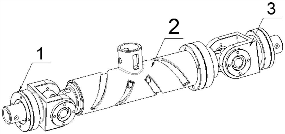
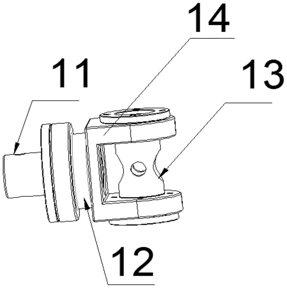
[0022] Such as figure 1 As shown in -4, a mechanical arm end effector includes a Hooke joint 1, a ball joint 3 and a connecting sleeve 2; the Hooke joint 1 and the ball joint 3 are installed on the connecting sleeve 2 Both ends; the connecting sleeve 2 includes a Hooke hinge side connecting rod 21, a ball hinge side connecting rod 22, a fastening flange 23, a support sleeve 24 and an intermediate connecting rod 25; the Hooke hinge side connecting rod 21 and the ball hinge side connecting rod 22 are respectively mounted on the left and right ends of the support sleeve 24, the middle part of the support sleeve 24 is hollow, and several spiral through holes 26 are set on the support sleeve 24, the tiger The tail ends of the hinge side connecting rod 21 and the ball hinge side connecting rod 22 are provided with rotating pins 27, and the rotating pins 27 are clamped in the spiral through holes 26, and the intermediate connecting rod 25 is installed in the supporting sleeve 24. Th...

Embodiment 2

[0026] The Hooke joint 1 and the ball joint 3 are slidably connected to the left and right ends of the connecting sleeve 2, the intermediate connecting rod 25 is slidably installed inside the support sleeve 24, and one end of the intermediate connecting rod 25 is connected to Hooke joint 1, the other end is connected to ball joint 3.

Embodiment 3

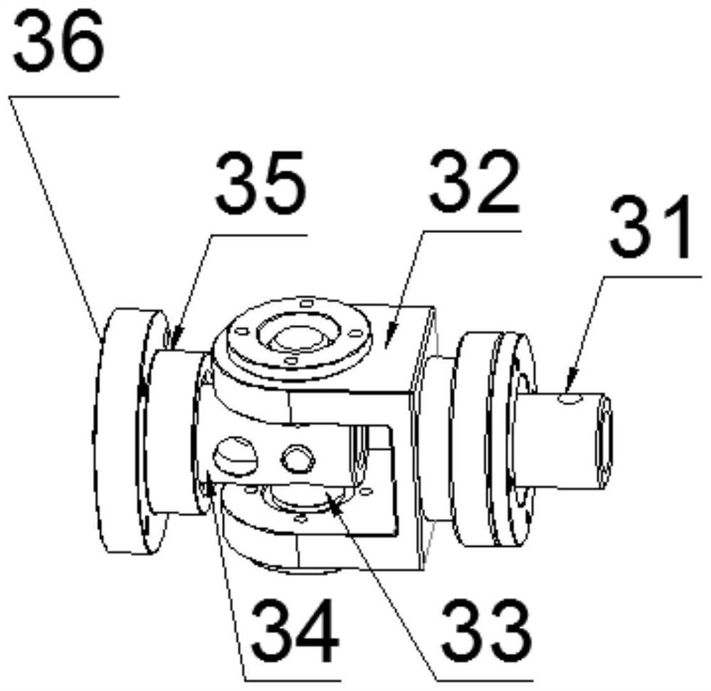
[0028] On the basis of Embodiment 1, the ball joint 3 includes a ball joint rotating rod one 31, a ball joint rotating shaft seat 32, a ball joint intermediate shaft 33, a ball joint rotating rod two 34, a ball joint rotating sleeve 35 and a fastening method Lan 2 36; the fastening flange 2 36 is fixedly socketed with the ball hinge sleeve 35, and the ball hinge sleeve 35 is sleeved on the ball head rotation rod 2 34, and the ball hinge shaft seat 32 passes through the ball hinge The intermediate rotating shaft 33 is rotationally connected with the ball joint rotating rod two 34, and one side of the ball joint rotating shaft seat 32 is provided with a rotating shaft bearing, and the described ball joint rotating rod one 31 is rotationally connected on the rotating shaft bearing to realize three-degree-of-freedom motion.

[0029] The second fastening flange 36 is fixedly connected with the first fastening flange 23 by screws.


PUM


Abstract

The invention discloses a mechanical arm tail end executing device. The mechanical arm tail end executing device comprises a hooke joint, a spherical hinge joint and a connecting sleeve. The hooke joint and the spherical hinge joint are installed at the left end and the right end of the connecting sleeve correspondingly. The connecting sleeve comprises a hooke joint side connecting rod, a spherical hinge side connecting rod, a first fastening flange, a supporting sleeve and a middle connecting rod. The hooke joint side connecting rod and the spherical hinge side connecting rod are installed at the left end and the right end of the supporting sleeve correspondingly. The middle of the supporting sleeve is hollow. A plurality of through holes are formed in the supporting sleeve. The middle connecting rod is installed in the supporting sleeve. The first fastening flange is fixed to the right wall of the spherical hinge side connecting rod. A connecting pipe is arranged in the middle of the top end of the supporting sleeve. The mechanical arm tail end executing device is compact in structure, small in occupied space, wide in movement range, flexible in movement and capable of achieving the six-freedom-degree movement function of the tail end of the executing device.

Description

technical field [0001] The present invention relates to the technical field of automation, in particular to a mechanical arm end effector. Background technique [0002] The end effector of the robotic arm generally refers to any tool that is connected to the edge (joint) of the robotic arm and has a certain function. Including the gripper of the robotic arm, the quick change device of the robotic arm tool, the collision sensor of the robotic arm, the rotary connector of the robotic arm, etc. The mechanical arm belongs to an automatic mechanical device, which has been widely used in technical fields such as industrial manufacturing and medical treatment. There are various forms of robotic arms, but most of them have a common feature, that is, they can accept control instructions and perform corresponding operations somewhere in the three-dimensional or three-dimensional space according to the control instructions. The end of the existing mechanical arm is large in size and ...

Claims


Application Information

Patent Timeline
Patent Type & Authority Applications(China)
IPC IPC(8): B25J15/02
CPCB25J15/0206
Inventor 朱延河赵杰李长乐
Owner 洛阳尚奇机器人科技有限公司
Why Eureka
Try Eureka