Organic Optoelectronic Device Test Fixture

A technology of optoelectronic devices and test fixtures, which is applied in the direction of the measuring device casing, etc., can solve the problems of cumbersome operation, damage to devices, and the influence of air on photoelectric devices, and achieve the effect of low cost and flexible transformation

Active Publication Date: 2017-10-27
HARBIN INST OF TECH
View PDF11 Cites 1 Cited by
  • Summary
  • Abstract
  • Description
  • Claims
  • Application Information

AI Technical Summary

Problems solved by technology

[0003] The present invention is to solve the problem that the existing organic photoelectric device fixture will destroy the device, the photoelectric device is affected by the air during the test process, and the operation is cumbersome. Now it provides an organic photoelectric device test fixture

Method used


Image

  • Organic Optoelectronic Device Test Fixture
  • Organic Optoelectronic Device Test Fixture
  • Organic Optoelectronic Device Test Fixture

Examples


specific Embodiment approach 1

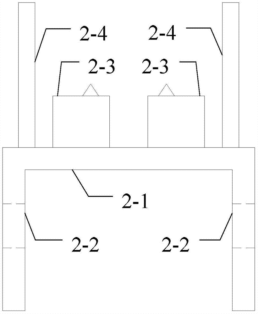
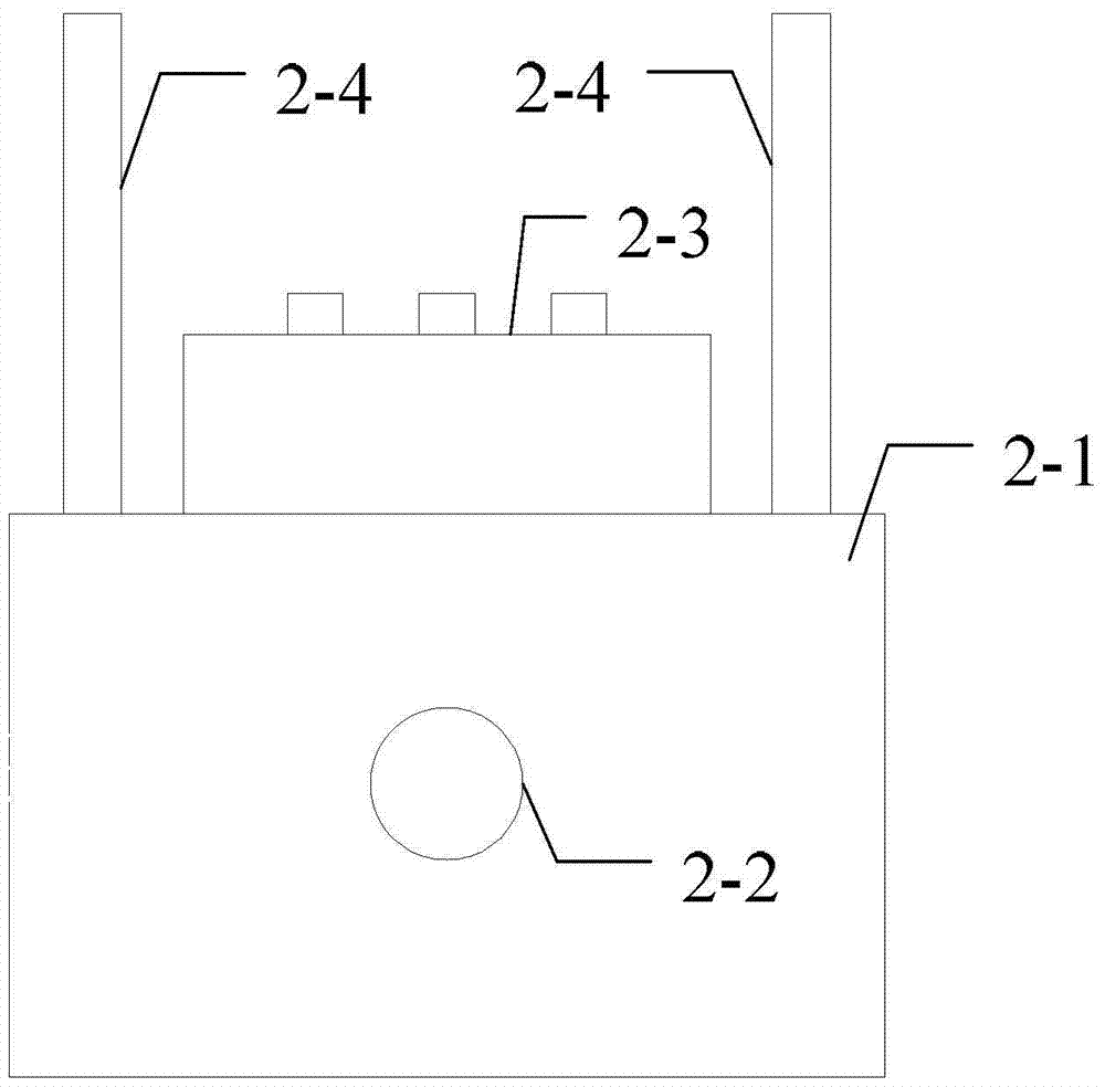
[0020] Specific implementation mode one: refer to Figure 1 to Figure 6 Specifically explain this embodiment, the organic photoelectric device test fixture described in this embodiment, it includes: a clamping part, a supporting part, a casing and an n-position switch 4;

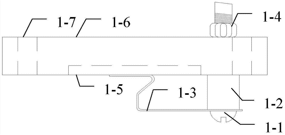
[0021] The clamping part includes: a screw 1-1, a support column 1-2, a straight cantilever spring piece 1-3, a nut 1-4 and a clamping plate 1-6;

[0022] There are screw holes, device slots 1-5 and a plurality of limit holes 1-7 on the clamping plate 1-6 respectively, and a positioning hole is opened at one end of the straight cantilever spring leaf 1-3, and the screws 1-1 pass through in turn The positioning hole of the straight cantilever spring leaf 1-3, the screw hole of the support column 1-2 and the clamping plate 1-6, and the screw 1-1 is fixed on the clamping plate 1-6 by the nut 1-4, and The straight cantilever spring piece 1-3 can rotate around the screw 1-1, and the bent end of the straight cant...

specific Embodiment approach 2

[0032] Embodiment 2: This embodiment is a further description of the organic optoelectronic device test fixture described in Embodiment 1. In this embodiment, an observation window is provided on the top cover 3-1.

[0033] The observation window in this embodiment is used to detect parameters such as luminance and color of the organic electro-reflective device during the testing process, or used for the light source entrance of the photovoltaic device.

specific Embodiment approach 3

[0034] Embodiment 3: This embodiment is a further description of the organic optoelectronic device test fixture described in Embodiment 2. In this embodiment, the material of the observation window is quartz.

[0035] In this embodiment, quartz is used as the light-transmitting material of the observation window, mainly because quartz absorbs less light, and the absorbed wavelength is below 200 nm, which ensures the light transmittance.


PUM


Abstract

An organic photoelectric device test fixture relates to the field of electric device testing. The invention aims to solve the problems that the existing organic photoelectric device fixture will destroy the device, the photoelectric device is affected by the air and the operation is cumbersome during the testing process. The organic optoelectronic device test fixture described in the present invention uses a miniature shrapnel type electrode column and a spring as a fixture to replace the crocodile clip, and the battery is tightly clamped between the two, so that the purpose of not destroying the battery and being able to test very small devices is achieved. ; The fixture is fixed in a sealed box, thereby realizing the inert gas sealing protection of the device; using a multi-speed switch with a plurality of miniature shrapnel electrode columns to achieve the purpose of semi-automatically testing the performance of organic photoelectric devices quickly and accurately. The test fixture of the present invention has the characteristics of low cost, no damage to devices, sealing inert gas protection, flexible transformation, semi-automation, etc., and is suitable for photoelectric performance testing of organic photoelectric devices of various sizes.

Description

technical field [0001] The invention relates to the field of photoelectric device testing, in particular to a test fixture for organic photoelectric devices. Background technique [0002] Organic optoelectronic devices include OLED, OPV, OTFT, organic memory, perovskite solar cells, etc. These devices have been popular at home and abroad for their advantages such as wide source of materials, low production cost, low energy consumption, simple preparation process, and easy mass production. It occupies an important position in the research of science and technology and industry. Because organic optoelectronic devices such as OLED, OPV, OTFT, organic memory, and perovskite solar cells are very sensitive to conditions such as water and oxygen, the performance of the device will be seriously attenuated after being placed in humid air for a period of time. The fixtures are all tested in the open air, so that the organic photoelectric devices will interact with the water and oxyge...

Claims


Application Information

Patent Timeline
Patent Type & Authority Patents(China)
IPC IPC(8): G01R1/04
Inventor 叶腾凌王军海
Owner HARBIN INST OF TECH
Why Eureka
Try Eureka