Eureka AIR delivers breakthrough ideas for toughest innovation challenges, trusted by R&D personnel around the world.

Novel high-pressure two-position two-way straight-through type mechanical pneumatic control valve

A two-position, two-way, air-operated valve technology, applied to multi-way valves, mechanical equipment, valve devices, etc., can solve the problem of difficult sealing of the air inlet and air outlet

Inactive Publication Date: 2015-10-28
SHENZHEN PINCHUAN ENERGY ELECTRIC CO LTD
View PDF5 Cites 4 Cited by
  • Summary
  • Abstract
  • Description
  • Claims
  • Application Information

AI Technical Summary

Problems solved by technology

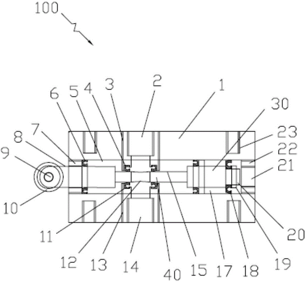
[0003] The purpose of the present invention is to overcome the defects of the prior art, to provide a unique design, novel structure, simple and compact, high air pressure, smooth ventilation, good sealing, which solves the problem of the air inlet and outlet of the existing traditional air control valve. It is difficult to solve the problem of sealing between shaft holes at the same hole position, and it is a new type of high-pressure two-position two-way straight-through mechanical air control valve that meets the mechanical power requirements of pneumatic control.

Method used


Image

  • Novel high-pressure two-position two-way straight-through type mechanical pneumatic control valve

Examples


Embodiment Construction

[0014] The following will clearly and completely describe the technical solutions in the embodiments of the present invention with reference to the accompanying drawings in the embodiments of the present invention. Obviously, the described embodiments are only some, not all, embodiments of the present invention. Based on the embodiments of the present invention, all other embodiments obtained by persons of ordinary skill in the art without making creative efforts belong to the protection scope of the present invention.

[0015] The new high-pressure two-position two-way straight-through mechanical air control valve is a commonly used switching device in modern industrial pipelines. It can be widely used in places without power supply, inflammable and explosive places, aerospace, offshore oil wells, power plants, oil fields, coal mines, and various mechanical air pipes. Road equipment, pharmaceuticals, papermaking, metallurgy, chemical industry, printing and dyeing, sewage treat...


PUM


Abstract

The invention provides a novel high-pressure two-position two-way straight-through type mechanical pneumatic control valve. The novel high-pressure two-position two-way straight-through type mechanical pneumatic control valve comprises a pneumatic control valve body, a pneumatic control valve shaft mounted in the pneumatic control valve body, a top shaft rolling bearing for driving the pneumatic control valve shaft, a piston and a connecting shaft connecting the pneumatic control valve shaft with the piston, wherein a valve shaft air hole is formed in the connecting shaft; a flat valve shaft air-closing end surface is arranged on the connecting shaft; the valve shaft air hole and the valve shaft air-closing end surface are arranged on the same plane; when the pneumatic control valve shaft slides left and right, the ventilating and the closing of the air are controlled; the valve shaft air hole is sealed by an air inlet sealing ring at the upper part and an air outlet sealing ring at the lower part, wherein a sealing clearance between the valve shaft air hole and the air inlet sealing ring can be changed by adjusting a first adjusting screw, and a sealing clearance between the valve shaft air hole and the air outlet sealing ring can be changed by adjusting a second adjusting screw; an air inlet valve opening and an air outlet valve opening are respectively formed above and below the valve shaft air hole. The novel high-pressure two-position two-way straight-through type mechanical pneumatic control valve solves the problems that a zigzag air path is formed by misalignment of an air inlet and an air outlet of a conventional pneumatic control valve, and the space of an air chamber is small, so that the pneumatic control valve can bear high air pressure under high pressure and at high speed, is smooth in ventilating and has the advantages of small resistance force, high efficiency, good sealing property, and stable work.

Description

technical field [0001] The invention relates to the field of air control valves, in particular to a novel high-pressure two-position two-way straight-through mechanical air control valve. Background technique [0002] The high-pressure air control valve is an important part of the air control system. Due to the low viscosity of the gas, it is easy to leak. When the air pressure in the air system is high, the sealing and durability of the air control valve become prominent problems. On the one hand, the air path is generally sealed around the valve shaft, and the seal is touched up and down. The misalignment between the air inlet and the air outlet forms a tortuous air path and the air path space is small and the control method is relatively complicated. Often, the frictional resistance is large, the damage rate of the sealing ring is high, The gas is blocked, resulting in poor ventilation, low air pressure, high gas loss, and short life. Especially in the case of high-speed ...

Claims


Application Information

Patent Timeline
Patent Type & Authority Applications(China)
IPC IPC(8): F16K11/065
CPCF16K11/0655
Inventor 齐靓王丽君齐东才朱红锋
Owner SHENZHEN PINCHUAN ENERGY ELECTRIC CO LTD
Why Eureka
Eureka Blog
Learn More