A large-section wire stripper

A technology of wire stripper and large cross section, which is applied in the direction of line/collector parts, equipment for dismantling/armored cables, electrical components, etc. Flattening, the effect of reducing crimp quality

Active Publication Date: 2019-02-05
CHINA ELECTRIC POWER RES INST +2
View PDF7 Cites 0 Cited by
  • Summary
  • Abstract
  • Description
  • Claims
  • Application Information

AI Technical Summary

Problems solved by technology

Although the prior art has a cross-section of 900mm 2 and 1000mm 2 The wire stripping technique of the wire, but for a section of 1520mm 2 There are still many deficiencies in the stripping technology of large cross-section wires. On the one hand, this is due to the particularity of the structure of the wire itself, and the large ratio of conductor cross-section to aluminum-steel; on the other hand, it is caused by the structure of the existing wire stripper.

Method used


Image

  • A large-section wire stripper
  • A large-section wire stripper
  • A large-section wire stripper

Examples


Embodiment Construction

[0032] The specific implementation manners of the present invention will be further described in detail below in conjunction with the accompanying drawings.

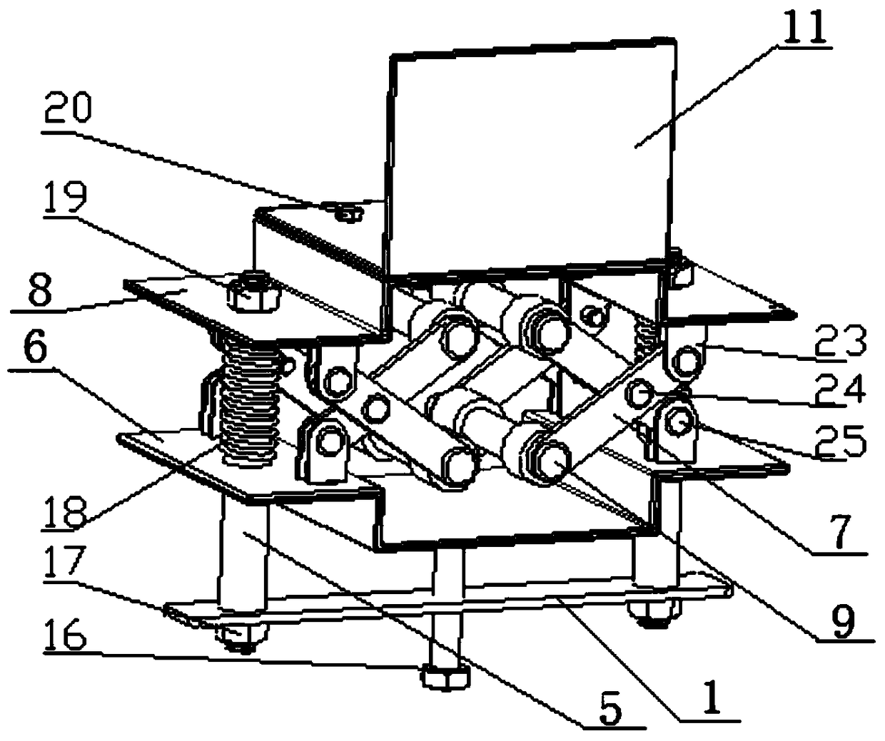
[0033] The large-section wire stripper that the embodiment of the present invention provides, such as Figures 1 to 4 As shown, the large-section wire stripper includes a clamping mechanism, a clamping mechanism and a pressing mechanism.

[0034] The clamping mechanism includes: a pressure plate 1, a guide column 5, a fixture bottom plate 6, a connecting rod 7, a fixture top plate 8 and a roller 9, and the pressure plate 1, the fixture bottom plate 6 and the fixture top plate 8 are arranged in parallel from bottom to top. The vertically arranged guide column 5 is connected, and the clamping mechanism is arranged horizontally between the fixture bottom plate 6 and the fixture top plate 8; the fixture top plate 8 is vertically provided with a fixture connecting plate 11, and a vertical pressing mechanism is arranged on the...


PUM


Abstract

A large-section conductor stripper. The stripper comprises a clamping mechanism, a conductor clamping mechanism, and a down-pressing mechanism. The clamping mechanism comprises a pressing plate (1), a clamp bottom plate (6), and a clamp top plate (8), which are disposed from bottom to top in parallel. The pressing plate, the clamp bottom plate, and the clamp top plate are connected by means of guide pillars (5) vertically disposed on two sides thereof, respectively. The conductor clamping mechanism is horizontally disposed between the clamp bottom plate and the clamp top plate. A clamp connecting plate (11) is vertically disposed at the top of the clamp top plate. The down-pressing mechanism is vertically disposed on the clamp connecting plate. Clamping arms are disposed between the clamp top plate and the clamp bottom plate and located on the two sides of the inlet and outlet ends of the conductor clamping mechanism respectively. The clamping arms are formed by intersecting connecting rods (7). Rollers (9) coaxial with the conductor clamping mechanism are disposed between the ends of the connecting rods on the same side of the inlet and outlet ends of the conductor clamping mechanism.

Description

technical field [0001] The invention relates to a wire stripper, in particular to a 1520mm wire stripper for overhead power transmission lines 2 Large cross-section wire stripper for wires. Background technique [0002] Power transmission is achieved by using a transformer to boost the power generated by the generator, and then connecting it to the transmission line through circuit breakers and other control equipment. According to the structural form, transmission lines are divided into overhead transmission lines and cable lines. The overhead transmission line is composed of line towers, wires, insulators, line fittings, guy wires, tower foundations, grounding devices, etc., and is erected above the ground. Compared with cable lines, the construction cost of overhead transmission lines is low, the construction period is short, and it is easy to repair and maintain. Therefore, overhead line transmission is the main transmission method adopted since the development of the...

Claims


Application Information

Patent Timeline
Patent Type & Authority Patents(China)
IPC IPC(8): H02G1/12H01R43/28
CPCH01R43/28H02G1/12
Inventor 汤广瑞江明万建成郝玉靖秦剑马一民胡春华彭飞倪达郭丙壬陈平
Owner CHINA ELECTRIC POWER RES INST
Why Eureka
Try Eureka