Experiment apparatus and experiment method for light transmission thermal lens effect in non-uniform temperature field
A technology of thermal lens effect and experimental equipment, applied in the direction of educational appliances, instruments, teaching models, etc., can solve problems that are difficult to realize, affect profound understanding, and have not been seen, and achieve a simple method, simple structure, and strong participation Effect
- Summary
- Abstract
- Description
- Claims
- Application Information
AI Technical Summary
Problems solved by technology
Method used
Image
Examples
Embodiment 1
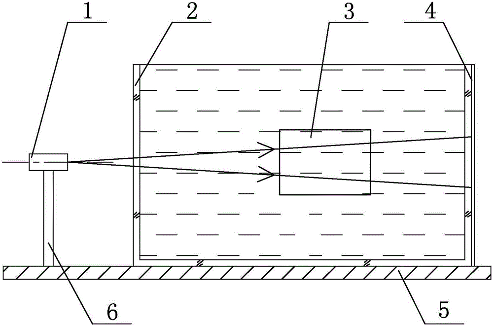
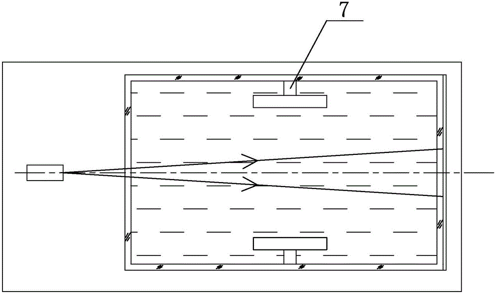
[0025] exist figure 1 , 2 Among them, the thermal lens effect experimental device for light transmission in a non-uniform temperature field in this embodiment is composed of a semiconductor laser 1, a transparent water tank 2, a semiconductor cooling chip 3, a coordinate paper 4, a base 5, a laser bracket 6, and a semiconductor cooling chip bracket 7. .
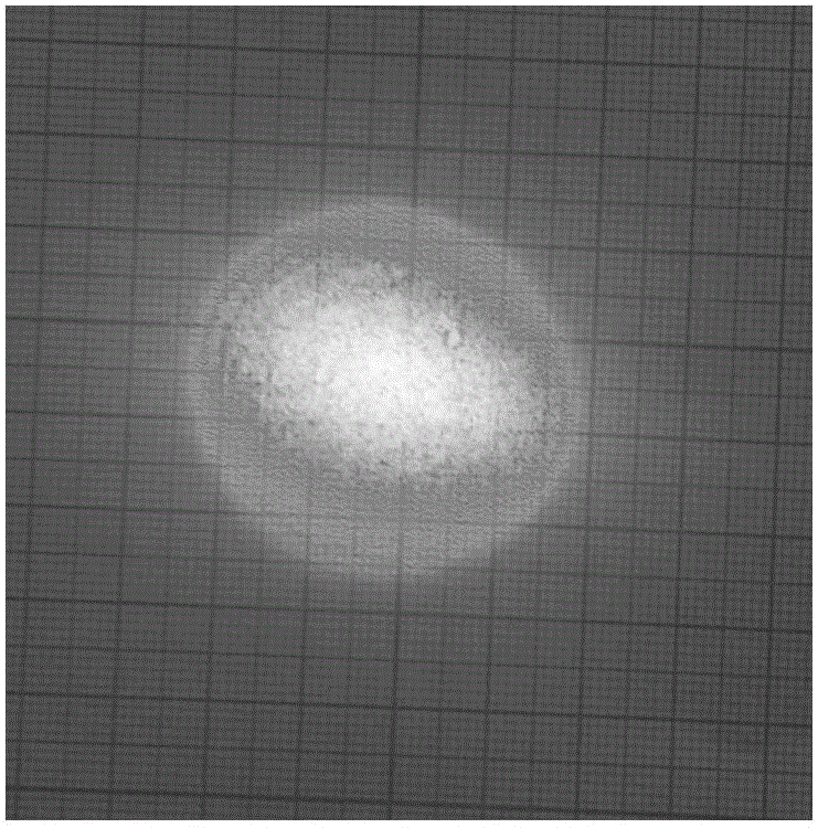
[0026] A transparent water tank 2 is placed on the base 5, and the transparent water tank 2 is made of plexiglass, and can also be made of quartz glass. The geometric shape of the transparent water tank 2 is a cuboid, and the transparent water tank 2 is filled with water. A coordinate paper 4 is pasted on the side with transparent glue, and the coordinate paper 4 is used to display the shape of the projected spot. On the front side wall in the transparent water tank 2, a semiconductor cooling chip support 7 is fixedly installed, and on the rear side wall in the transparent water tank 2, a semiconductor cooling chip bracket ...
Embodiment 2
[0037]On the front side wall in the transparent water tank 2, a semiconductor cooling chip support 7 is fixedly installed, and on the rear side wall in the transparent water tank 2, a semiconductor cooling chip bracket 7 is fixedly installed, and each semiconductor cooling chip bracket 7 is used The threaded fastening connector is fixedly connected with a semiconductor cooling chip 3, the semiconductor cooling chip bracket 7 and the semiconductor cooling chip 3 are immersed in water, the distance from the upper surface of the semiconductor cooling chip 3 to the water surface is 100mm, and the geometric shape of the two semiconductor cooling chips 3 And the position in the transparent water tank 2 is the same as that of Embodiment 1, the front sides of the two semiconductor refrigeration chips 3 are hot surfaces, the front sides are perpendicular to the horizontal plane, and parallel to the length front side walls of the transparent water tank 2, and the two semiconductor refrige...
Embodiment 3
[0044] On the front side wall in the transparent water tank 2, a semiconductor cooling chip support 7 is fixedly installed, and on the rear side wall in the transparent water tank 2, a semiconductor cooling chip bracket 7 is fixedly installed, and each semiconductor cooling chip bracket 7 is used The threaded fastening connector is fixedly connected with a semiconductor cooling chip 3, the semiconductor cooling chip bracket 7 and the semiconductor cooling chip 3 are immersed in water, the distance from the upper surface of the semiconductor cooling chip 3 to the water surface is 100mm, and the geometric shape of the two semiconductor cooling chips 3 And the position in the transparent water tank 2 is the same as that of Embodiment 1, the front sides of the two semiconductor refrigeration chips 3 are hot surfaces, the front sides are perpendicular to the horizontal plane, and parallel to the length front side walls of the transparent water tank 2, and the two semiconductor refrig...
PUM
 Abstract
Description
Claims
Application Information
 - R&D Engineer
- R&D Manager
- IP Professional
- Industry Leading Data Capabilities
- Powerful AI technology
- Patent DNA Extraction
Browse by: Latest US Patents, China's latest patents, Technical Efficacy Thesaurus, Application Domain, Technology Topic, Popular Technical Reports.
© 2024 PatSnap. All rights reserved.Legal|Privacy policy|Modern Slavery Act Transparency Statement|Sitemap|About US| Contact US: help@patsnap.com


