
compressor

A compressor and compression cavity technology, applied in the field of compressors, can solve the problems of reduced energy efficiency of compressors and increased compression power of compressors, achieving the effect of reducing compression power and improving energy efficiency

Active Publication Date: 2017-05-31
GUANGDONG MEIZHI COMPRESSOR +1
View PDF6 Cites 0 Cited by
  • Summary
  • Abstract
  • Description
  • Claims
  • Application Information

AI Technical Summary

Problems solved by technology

During the compression process, the larger the piston rotation angle, the higher the temperature of the refrigerant in the discharge chamber. When the piston rotation angle increases to a certain angle, the temperature of the refrigerant in the discharge chamber is higher than the ambient temperature of the compressor. In the subsequent compression During the process, the compression power of the compressor increases, and the energy efficiency of the compressor decreases

Method used


Image

  • compressor
  • compressor
  • compressor

Examples


Embodiment Construction

[0027] The following describes in detail the embodiments of the present invention, examples of which are illustrated in the accompanying drawings, wherein the same or similar reference numerals refer to the same or similar elements or elements having the same or similar functions throughout. The embodiments described below with reference to the accompanying drawings are exemplary, only used to explain the present invention, and should not be construed as a limitation of the present invention.

[0028] In the description of the present invention, it should be understood that the terms "center", "longitudinal", "lateral", "length", "width", "thickness", "upper", "lower", "front", " Back, Left, Right, Vertical, Horizontal, Top, Bottom, Inner, Outer, Clockwise, Counterclockwise, Axial , "radial", "circumferential" and other indicated orientations or positional relationships are based on the orientations or positional relationships shown in the accompanying drawings, and are only f...


PUM


Abstract

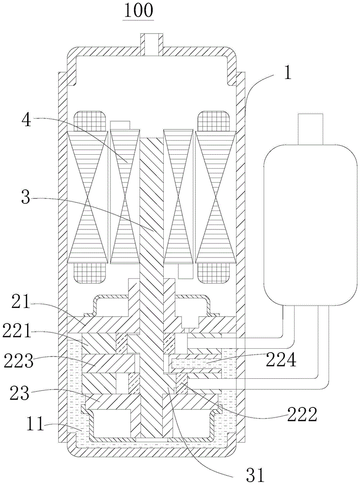
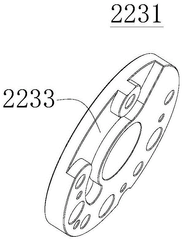
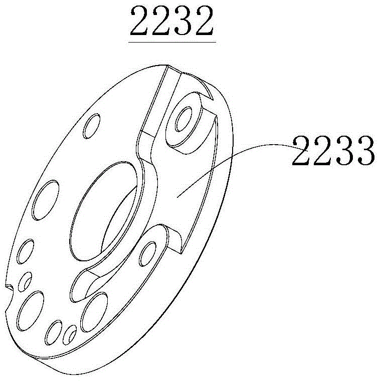
The invention discloses a compressor which comprises a shell and a compression mechanism. An oil pool is arranged in the shell. The compression mechanism comprises a main bearing, an air cylinder assembly and an auxiliary bearing. The main bearing is arranged on the top of the air cylinder assembly, and the auxiliary bearing is arranged at the bottom of the air cylinder assembly. The air cylinder assembly comprises two vertically-arranged air cylinders. Each air cylinder is provided with a compression cavity and a sliding piece groove. Each compression cavity is internally provided with a piston. Each piston can roll along the inner wall of the corresponding compression cavity. The compression cavity comprises a suction cavity and an exhaust cavity. A slip piece is movably arranged in each slip piece groove, and the front end of the slip piece abuts against the outer circumferential wall of the corresponding piston. A partition plate is arranged between the two air cylinders. The partition plate is provided with a cavity communicated with the oil pool. According to the compressor, the compression power needed in the compression process of the compressor can be reduced, and the energy efficiency of the compressor is improved.

Description

technical field [0001] The present invention relates to the technical field of compressors, in particular to a compressor. Background technique [0002] In the related art, the compressor drives the piston to rotate through the crankshaft to compress the refrigerant. During the compression process, the larger the piston rotation angle, the higher the temperature of the refrigerant in the exhaust chamber. When the piston rotation angle increases to a certain angle, the temperature of the refrigerant in the exhaust chamber is higher than the ambient temperature where the compressor is located. During the process, the compression power of the compressor increases, and the energy efficiency of the compressor decreases. SUMMARY OF THE INVENTION [0003] The present invention aims to solve at least one of the technical problems existing in the prior art. Therefore, an object of the present invention is to provide a compressor, which can reduce the compression power of the comp...

Claims


Application Information

Patent Timeline
Patent Type & Authority Patents(China)
IPC IPC(8): F04C18/356F04C29/04F04C29/02
Inventor 蒋君之高斌余彧
Owner GUANGDONG MEIZHI COMPRESSOR
Learn More