Building mortar conveyer

A conveying device and mortar technology, applied in the direction of cleaning device, transportation and packaging, conveyor objects, etc., can solve the problems of damaging the bearing lubrication conditions, increasing the running resistance of the roller, and poor cleaning effect, so as to optimize the working environment and reduce labor Cost, the effect of ensuring delivery efficiency

Inactive Publication Date: 2015-10-21
WENZHOU UNIVERSITY
View PDF10 Cites 7 Cited by
  • Summary
  • Abstract
  • Description
  • Claims
  • Application Information

AI Technical Summary

Problems solved by technology

When the belt conveyor transports viscous substances such as coal slurry and mortar, the viscous substances such as coal slurry and mortar will adhere to the surface of the belt. Conveying efficiency; At the same time, when the slime, mortar and other viscous materials on the belt working surface are inconvenient to clean due to the long-term operation of the belt, a lot of materials will accumulate on the belt working surface, and these viscous materials will enter the roller bearing and damage the bearing. Lubrication conditions increase the running resistance of the drum, causing the bearing to get stuck, causing the drum to not rotate. After the non-rotating drum shell is worn and damaged, the belt will be scratched
At present, the sticky material on the belt is generally cleaned manually. Because of safety considerations, the belt is usually cleaned after the belt stops working. This cleaning method has high labor costs and low efficiency.
There is also a scraper fixed at one end of the conveyor belt. When the belt passes through the scraper, the sticky material is scraped off by the scraper. However, the cleaning effect of this method is not good, and the sticky material is often not cleaned, and the scraped material cannot be collected. , causing waste, materials spilled on the ground, polluting the working environment

Method used


Image

  • Building mortar conveyer
  • Building mortar conveyer
  • Building mortar conveyer

Examples


Embodiment Construction

[0014] The present invention will be further described below in conjunction with the accompanying drawings and embodiments, but not as a basis for limiting the present invention.

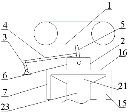
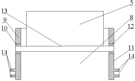
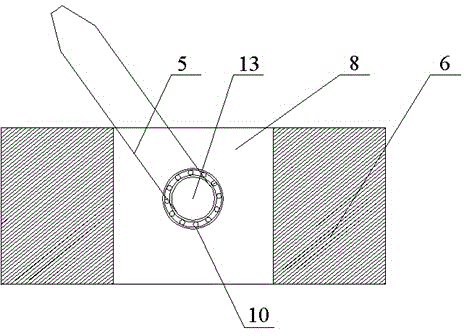
[0015] Example. A conveying device for construction mortar, constituted as Figure 1-6 As shown, a conveyor belt 1 is included, and a cleaner 2 is provided under the conveyor belt 1; the cleaner 2 includes a crank 3, the crank 3 is connected to the rocker 4, the rocker 4 is connected to the scraper 5, and the scraper 5 is connected to the slider 6 connection, the slider 6 is flexibly connected with the bracket 7, the slider 6 is provided with a cavity 8, the left side wall 9 of the cavity 8 is provided with a first bearing 10, and the right side wall 11 is provided with a second bearing 12. A shaft 13 is provided between the first bearing 10 and the second bearing 12, and the shaft 13 is connected to the scraper 5. There are protrusions 14 on the outside of the left side wall 9 and the right si...


PUM


Abstract

The invention discloses a building mortar conveyer. The building mortar conveyor comprises a conveyer belt, and a cleaner is disposed under the conveyer belt. A crank of the cleaner is connected with a rocker, a rocker is connected with a scraper plate, the scraper plate is connected with a sliding block, the sliding block is movably connected with a support, a shaft is disposed in a cavity of the sliding block, the shaft is connected with the scraper plate, and outer sides of the left side wall and the right side wall are provided with bumps. The support comprises columns, bottoms of the columns are provided with a top board, a square chamber is disposed on the top board, inner sides of the left side wall and the right side wall of the square chamber are provided with guide rails matching with the bumps, a collecting chamber is disposed under the top board, side plates of the collecting chamber are connected with the top board of the support, and the collecting chamber is a taper chamber which is connected with a conveyer pipe. Material adhered on the conveyer belt of the conveyer can be cleaned up, the cleaning effect is good, and the scraped material can be collected without waste. The building mortar conveyer is low in labour cost and high in efficiency.

Description

technical field [0001] The invention relates to a conveying device for construction, in particular to a conveying device for building mortar. Background technique [0002] Belt conveyors, especially long-distance and large-capacity belt conveyors, are widely used in large and medium-sized coal mines and construction in my country. When the belt conveyor transports viscous substances such as coal slurry and mortar, the viscous substances such as coal slurry and mortar will adhere to the surface of the belt. Conveying efficiency; At the same time, when the slime, mortar and other viscous materials on the belt working surface are inconvenient to clean due to the long-term operation of the belt, a lot of materials will accumulate on the belt working surface, and these viscous materials will enter the roller bearing and damage the bearing. Lubricating conditions increase the running resistance of the drum, causing the bearing to get stuck, causing the drum to not rotate, and the...

Claims


Application Information

Patent Timeline
Patent Type & Authority Applications(China)
IPC IPC(8): B65G45/14B65G45/26
Inventor 沈文宝童小燕
Owner WENZHOU UNIVERSITY
Why Eureka
Try Eureka