Al technical title is built by PatSnap Al team. It summarizes the technical point description of the patent document.
A technology of ore mining and vibrating screen, which is applied in the direction of filter screen, solid separation, grille, etc., can solve the problems of decreased material screening recovery rate, increased operating frequency, and increased dumping times, so as to reduce labor intensity and reduce operating frequency , the effect of reducing the number of dumping
Active Publication Date: 2017-02-08
TONGLING ZHONGDU MINING CONSTR
View PDF5 Cites 2 Cited by
Summary
Abstract
Description
Claims
Application Information
AI Technical Summary
This helps you quickly interpret patents by identifying the three key elements:
Problems solved by technology
Method used
Benefits of technology
Problems solved by technology
When the material is dumped, a large impact force is generated, which can easily cause impact on the screen of the powder vibrating screen, resulting in shortened life of the screen and increased use costs
And when the material enters the screen, there will be a lot of dust, which will cause hidden dangers to the health of the operators and cause great pollution to the environment. The loss of materials due to dust will directly lead to a decrease in the recovery rate of material screening and an increase. Screening cost
In addition, it is necessary to make an accurate beam for how much material to dump on the sieve. If there is too much material to dump, it will cause the material to overflow the vibrating screen, resulting in unnecessary waste of material. The operating frequency also increases the labor intensity of the operator
Method used
Image
Click on the blue label to locate the original text in one second.
Reading with bidirectional positioning of images and text.
Examples
Embodiment Construction
[0018] The powder vibrating screen used for ore mining of the present invention will be clearly and completely described below in conjunction with the accompanying drawings.
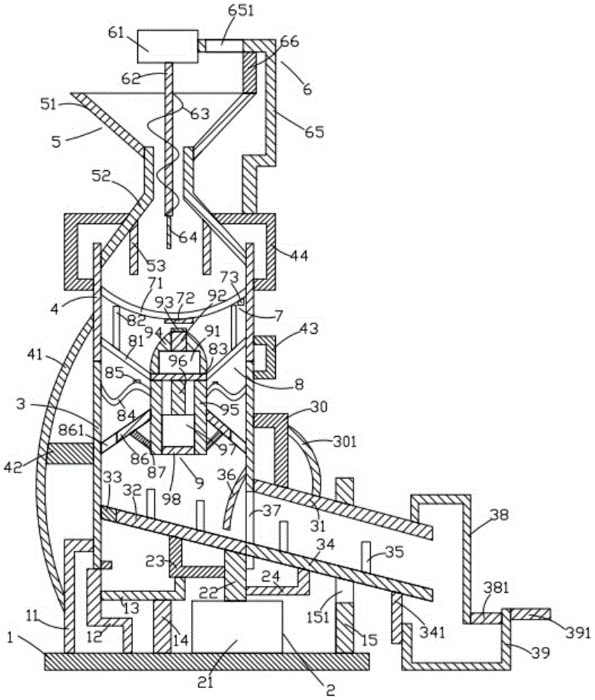
[0019] Such as figure 1 As shown, the powder vibrating screen used for ore mining in the present invention includes a base 1, a cylinder device 2 located above the base 1, a lower frame 3 located above the cylinder device 2, and a lower frame 3 located above the lower frame 3. The upper frame body 4, the feeding device 5 positioned above the upper frame body 4, the pushing device 6 positioned above the feeding device 5, the screen device 7 positioned below the feeding device 5, and the The screening device 8 below the screen device 7 and the pushing device 9 arranged on the screening device 8 .
[0020] Such as figure 1As shown, the base 1 is a cuboid, and the base 1 is placed horizontally. The base 1 is provided with a first bracket 11, a second bracket 12 on the right side of the first bracket 11, an...
PUM
Abstract
A powder vibrating screen for ore extraction, comprising a base (1), a cylinder device (2), a lower frame body (3), an upper frame body (4), a feeding device (5), a material pushing device (6), a mesh device (7), a screening device (8), and a pushing device (9); the base (1) being provided thereon with a first bracket (11), a second bracket (12), a third bracket (13), a first support pillar (14), and a second support pillar (15); the cylinder device (2) comprising a first cylinder (21), a first pushing rod (22), a fourth bracket (23), and a fifth bracket (24); the lower frame body (3) being provided thereon with a first support rod (30), a discharging frame (31), a first slant plate (32), a closing block (33), a second slant plate (34), a first filter plate (35), a first curved rod (36), a baffle (38), and a material receiving box (39); the upper frame body (4) being provided thereon with a second curved rod (41), a third cross rod (42), a first connection rod (43), and a first fixing frame (44); the feeding device (5) comprising a hopper (51), a material collection frame (52), and a second vertical rod (53); the material pushing device (6) comprising a first motor (61), a rotation shaft (62), a screw rod (63), a third vertical rod (64), a second fixing frame (65), and a third support pillar (66); and the mesh device (7) comprising a mesh (71), a first magnet (72), and a first vibrator (73). The frequency of toppling can be reduced, reducing the labor intensity of an operator.
Description
technical field [0001] The invention relates to the field of ore mining machinery, in particular to a powder vibrating screen used for ore mining. Background technique [0002] At present, the general powder vibrating screen in the market often pours the material from the discharge port of the processing powder material device (such as a reactor) directly onto the vibrating screen during work, and directly sieves. When the material is dumped, a large impact force is generated, which is easy to cause impact on the screen of the powder vibrating screen, resulting in shortened life of the screen and increased use costs. And when the material enters the screen, there will be a lot of dust, which will cause hidden dangers to the health of the operators and cause great pollution to the environment. The loss of materials due to dust will directly lead to a decrease in the recovery rate of material screening and an increase. screening cost. In addition, it is necessary to make an ...
Claims
Application Information
Patent Timeline
Application Date:The date an application was filed.
Publication Date:The date a patent or application was officially published.
First Publication Date:The earliest publication date of a patent with the same application number.
Issue Date:Publication date of the patent grant document.
PCT Entry Date:The Entry date of PCT National Phase.
Estimated Expiry Date:The statutory expiry date of a patent right according to the Patent Law, and it is the longest term of protection that the patent right can achieve without the termination of the patent right due to other reasons(Term extension factor has been taken into account ).
Invalid Date:Actual expiry date is based on effective date or publication date of legal transaction data of invalid patent.