


Quick Research
Generate reliable direction feasibility study reports for your R&D in just a few steps.

Technical Q&A
Discover and master advanced knowledge NOW. Basics, ideas, possibilities, all at once.

Find Solutions
As an expert in R&D theories, this can generate solutions to your technical problems instantly.

Evaluate Feasibility
Analyze your overall solution with one click, know your potential R&D risks in advance.

Monitor Landscape
Get weekly tech updates, stay abreast of the latest tech innovations and key insights.
LED drive device with valley fill circuit
A LED driving and valley-filling circuit technology, which is applied in the direction of lamp circuit layout, lighting devices, electric light sources, etc., can solve the problems of narrow conduction angle of rectifier diodes, distortion of AC input current, and reduction of active power, so as to achieve simple circuits and low cost. Total harmonic distortion, low cost effect
- Summary
- Abstract
- Description
- Claims
- Application Information
AI Technical Summary
Problems solved by technology
Method used
Image

Examples
Embodiment 1
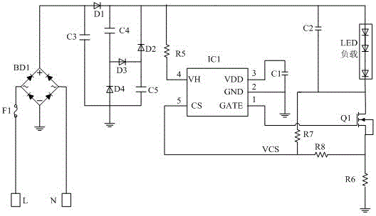
[0017] Such as figure 1 As shown, the LED driving device with a valley filling circuit in this embodiment includes a bridge rectifier module connected to the mains, a constant current module connected to the bridge rectifier module, a filter capacitor C3, an LED load and a valley filling circuit; Among them: the bridge rectifier module is a full-bridge rectifier bridge BD1, and the full-bridge rectifier bridge BD1 is a rectifier bridge that is connected and packaged as one by 4 rectifier diodes in the form of a bridge-type full-wave rectifier circuit, which has two inputs Terminal and two output terminals, the two output terminals are DC output positive pole and DC output negative pole respectively. The two input terminals of the full-bridge rectifier bridge stack BD1 are connected to the mains, respectively connected to the live line L and the neutral line N of the mains; the DC output negative pole of the full-bridge rectifier bridge stack BD1 is grounded; the DC output posi...
Embodiment 2
[0023] On the basis of Embodiment 1, the LED driving device in this embodiment further includes a diode D1 for isolating the valley filling circuit and the bridge rectifier module and a fuse F1 for surge protection.
[0024] The full-bridge rectifier bridge stack BD1 is connected to the live line L of the mains through the fuse F1. The fuse F1 has a certain resistance value, can absorb the peak voltage, and has the function of anti-surge.
[0025] The positive pole of the diode D1 is connected to the positive pole of the DC output of the full-bridge rectifier bridge stack BD1, and the negative pole is connected to the capacitor C4, the negative pole of the diode D2, the voltage dividing resistor R5, and the positive pole of the LED load. D1 is an isolation diode, which can separate the full-bridge rectifier bridge stack BD1 from the valley-filling circuit. The capacitor C3 is connected to the positive pole of the DC output of the full-bridge rectifier bridge stack BD1.
[002...
PUM
 Abstract
Description
Claims
Application Information
 - R&D Engineer
- R&D Manager
- IP Professional
- Industry Leading Data Capabilities
- Powerful AI technology
- Patent DNA Extraction
Browse by: Latest US Patents, China's latest patents, Technical Efficacy Thesaurus, Application Domain, Technology Topic, Popular Technical Reports.
© 2024 PatSnap. All rights reserved.Legal|Privacy policy|Modern Slavery Act Transparency Statement|Sitemap|About US| Contact US: help@patsnap.com