Simple and practical harmonic wave improved LED drive circuit

A kind of LED driving and practical technology, applied in the direction of lamp circuit layout, electric light source, lighting device, etc., can solve the problems of narrow conduction angle of rectifier diode, distortion of AC input current, power factor reduction, etc., to ensure active power, reduce Total harmonic distortion, the effect of improving harmonics

Inactive Publication Date: 2015-10-14
CHENGDU ETC CERTIFICATION GRP CO LTD
View PDF6 Cites 5 Cited by
  • Summary
  • Abstract
  • Description
  • Claims
  • Application Information

AI Technical Summary

Problems solved by technology

Due to the existence of large-capacity filter capacitors, the conduction angle of the rectifier diode becomes very narrow, and it can only be turned on near the peak value of the AC input voltage, resulting in severe distortion of the AC input current and becoming a peak pulse.
This current waveform contains a large number of harmonic components, which not only pollutes the power grid, but also leads to a significant reduction in the output active power after filtering, which greatly reduces the power factor.

Method used


Image

  • Simple and practical harmonic wave improved LED drive circuit

Examples


Embodiment 1

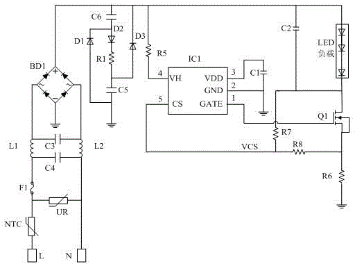
[0017] Such as figure 1 As shown, the simple and practical harmonic improved LED drive circuit of this embodiment includes a bridge rectifier module, a constant current module connected to the bridge rectifier module, an LED load, an electromagnetic interference filter and a valley filling circuit; wherein: The bridge rectifier module has two input terminals and two output terminals. The two output terminals are DC output positive pole and DC output negative pole respectively. The two input terminals are connected to the mains through the electromagnetic interference filter, and the DC output positive pole is connected to the constant current at the same time. flow modules, LED loads and valley fill circuits.

[0018] The constant current module includes a constant current control chip IC1, a MOS transistor Q1, a voltage dividing resistor R5, an adjusting resistor R6, a sampling resistor R7, and a sampling resistor R8; the positive pole of the LED load is connected to the posi...

Embodiment 2

[0024] On the basis of Embodiment 1, the small LED drive circuit in this embodiment also includes a fuse F1 for surge protection, a thermistor NTC, and a varistor UR. The fuse F1 and the thermistor NTC are inductively connected in series and the fuse F1 Connect the inductor L1, the thermistor NTC is connected to the live line L of the mains; one end of the varistor UR is connected to the neutral line N of the mains, and the other end is connected between the fuse F1 and the thermistor NTC.

[0025] In order to avoid the inrush current generated when the circuit is turned on, a power type thermistor NTC is connected in series in the power supply circuit, which can effectively suppress the inrush current when the circuit is turned on, and the thermistor The resistance value of NTC will be reduced to a very small level, and the power consumed by it can be ignored, and it will not affect the normal working current.


PUM


Abstract

The invention discloses a simple and practical harmonic wave improved LED drive circuit. The circuit includes a bridge rectification module, and a constant current module, an LED load, an electromagnetic interference filter and a valley fill circuit that are connected to the bridge rectification module. The bridge rectification module is connected to commercial power through the electromagnetic interference filter. The valley fill circuit is connected to the output end of the bridge rectification module. The electromagnetic interference filter is in series connection between an AC wire inlet end and the bridge rectification module to filter electromagnetic interference, harmonic waves are improved by improving of a conduction angle input to a rectification filter circuit, the valley fill circuit is utilized to fill the circuit, and total harmonic wave distortion is minimized. Therefore, harmonic wave components are prevented from polluting a power grid, and active power is guaranteed. The drive circuit has the advantages of simple structure and low cost.

Description

technical field [0001] The invention relates to the field of LED drive circuits, in particular to a simple and practical harmonic improvement type LED drive circuit. Background technique [0002] As a new type of green light source, LED light source has been more and more widely used due to its advantages of low power consumption, long life, fast response, high efficiency and energy saving. [0003] Under the same brightness, the LED light source consumes only one tenth of the power of ordinary incandescent lamps, but its life can be extended by 100 times. But its life is largely determined by the driving power supply, so a reliable, high conversion efficiency, and long-life LED driving power supply is very important for LED light sources. [0004] At present, the power supply method of LED lamps mostly adopts DC, and the mains power supply needs to be converted into DC through a rectifier bridge, and then drive the LED lamp beads to emit light through a driving circuit. I...

Claims


Application Information

Patent Timeline
IPC IPC(8): H05B37/02
Inventor 黄其
Owner CHENGDU ETC CERTIFICATION GRP CO LTD
Why Eureka
Try Eureka