
Dye molecule detection method

A technology of molecular detection and dyes, applied in the direction of material excitation analysis, Raman scattering, etc.

Inactive Publication Date: 2015-10-14
RES CENT FOR ECO ENVIRONMENTAL SCI THE CHINESE ACAD OF SCI
View PDF3 Cites 4 Cited by
  • Summary
  • Abstract
  • Description
  • Claims
  • Application Information

AI Technical Summary

Problems solved by technology

But so far, the use of microorganisms to reduce gold and silver nanoparticles in situ and use them as SERS substrates to detect dye molecules has not been reported.

Method used


Image

  • Dye molecule detection method
  • Dye molecule detection method
  • Dye molecule detection method

Examples


Embodiment 1

[0017] Example 1 Preparation of LB medium: 1 g of peptone, 0.5 g of yeast and 1 g of sodium chloride were weighed and dissolved in 100 mL of deionized water, and the pH value was adjusted to about 7. Stored after high temperature and high pressure sterilization. Microbial strain culture: use a sterilized inoculation loop to insert the frozen-preserved strain Pantoea sp.IMH into a sterilized Erlenmeyer flask containing 100 mL of LB medium. The Erlenmeyer flask was placed in a shaker at 30° C. and 150 rpm for 12 hours to activate the strain. After the activation is completed, transfer 1 mL of the bacterial liquid to a sterilized Erlenmeyer flask containing 100 mL of fresh LB medium, and continue to place the Erlenmeyer flask into a shaker at 30°C and 150 rpm for shaking culture. Microbial in situ reduction synthesis of gold nanoparticles: Take 10 mL of bacterial solution grown to the logarithmic phase in a 15 mL centrifuge tube, and centrifuge for 3 minutes at a speed of 8000 r...


PUM

PropertyMeasurementUnit
particle diameteraaaaaaaaaa

Abstract

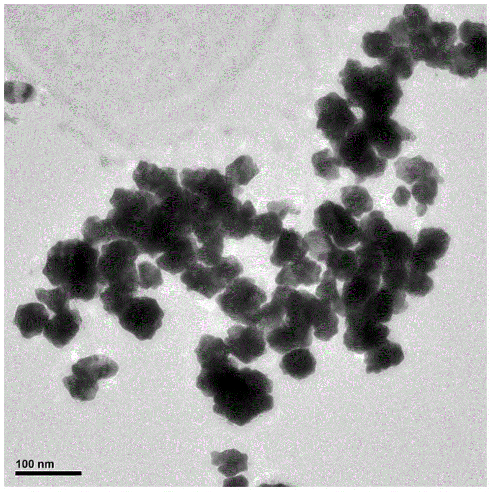
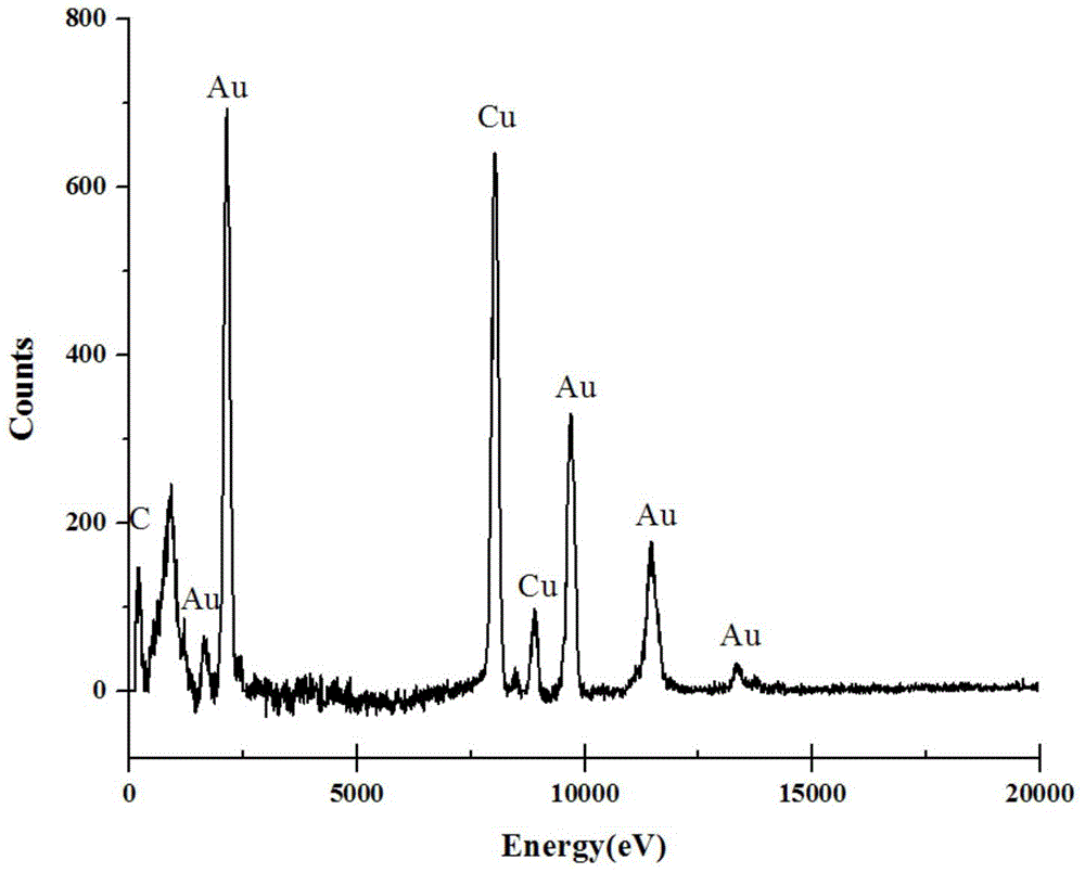
A dye molecule detection method includes the steps of (1) synthesizing gold nano particles through a method of in-situ reduction of chloroauric acid with a bacteria strain Pantoea sp.IMH; (2) with the gold nano particles as a surface enhanced Raman substrate, mixing the gold nano particles with dye molecules; and (3) detecting a Raman characteristic peak of the dye molecules through a portable Raman spectrometer, thereby achieving the detection of four kinds of dye molecules.

Description

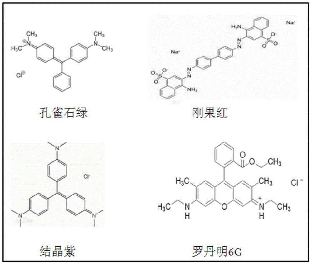
technical field [0001] The invention relates to a method for detecting dye molecules by using a surface-enhanced Raman spectroscopy (SERS) technique, especially a method for detecting malachite green, Congo red, crystal violet and rhodamine 6G. technical background [0002] Surface Enhanced Raman Spectroscopy (SERS) technology is developed based on the enhancement of the Raman signal of the molecule to be measured caused by the rough noble metal surface. By observing the SERS signal of the analyte molecules on the surface of the substrate material, the material composition and structure of the analyte can be determined. The rapid development of nanotechnology has led to breakthroughs in both basic research and practical application of surface-enhanced Raman technology. A large number of literatures have reported that nanoscale particles as SERS substrates can achieve an enhancement factor of 1014-1015, thereby meeting the detection requirements at the single-molecule level,...

Claims


Application Information

Patent Timeline
Patent Type & Authority Applications(China)
IPC IPC(8): G01N21/65
Inventor 景传勇刘文婧杜晶晶
Owner RES CENT FOR ECO ENVIRONMENTAL SCI THE CHINESE ACAD OF SCI
Learn More