
Method and system for vehicle battery environment control

A vehicle and environment technology, applied in the field of environment control, can solve the problems of battery energy consumption, cooling battery, etc., and achieve the effect of prolonging power consumption and simplifying control

Inactive Publication Date: 2015-10-14
FORD GLOBAL TECH LLC
View PDF4 Cites 0 Cited by
  • Summary
  • Abstract
  • Description
  • Claims
  • Application Information

AI Technical Summary

Problems solved by technology

However, the battery enclosure environmental controller consumes battery energy to cool the battery

Method used


Image

  • Method and system for vehicle battery environment control
  • Method and system for vehicle battery environment control
  • Method and system for vehicle battery environment control

Examples


Embodiment Construction

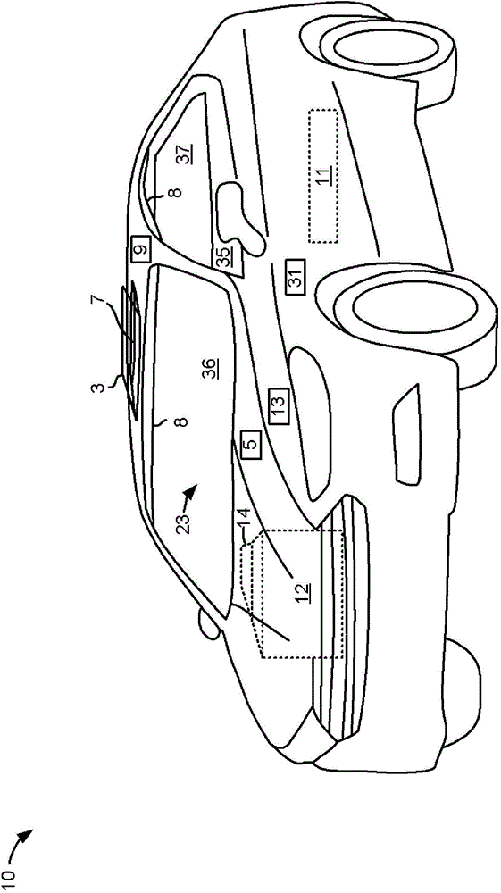
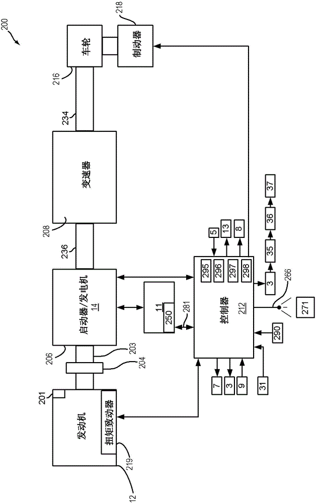
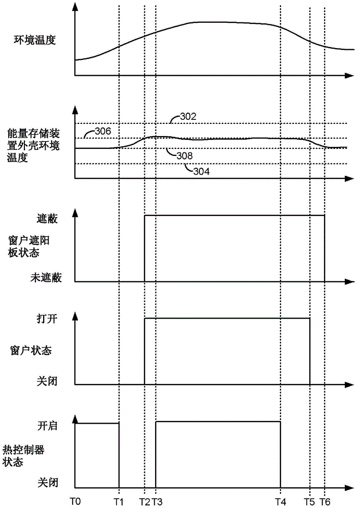
[0025] The present invention relates to providing climate or environmental control for vehicle energy storage device enclosures. In particular, methods and systems for providing heating and cooling to an energy storage device housing of a vehicle are described. The energy storage device may be located outside or inside the passenger cabin or compartment of the vehicle. exist figure 1 An exemplary passenger vehicle is shown in . The vehicle can include as in figure 2 The drive train shown in . can be as image 3 Conditions within the housing of the energy storage device are controlled as shown in the sequence of . Figure 4 and Figure 5 A method for controlling conditions within an energy storage device enclosure is shown in . At last, Figure 6A and Figure 6B An exemplary configuration for delivering air to an energy storage device housing of a vehicle is shown.

[0026] refer to figure 1 , shows a vehicle 10 including an engine 12 , an electric machine 14 and an...


PUM


Abstract

Methods and system for controlling conditions within an enclosure housing a vehicle propulsion energy source are described. In one example, vehicle windows, vents, and shades may be operated to reduce an amount of energy used to maintain conditions within an enclosure housing a vehicle propulsion source. The systems and methods may be at least incorporated into electric and hybrid vehicles.

Description

technical field [0001] The present invention relates to methods and systems for improving the control of the environment within a vehicle battery enclosure. The method and system can be used to conserve energy stored in batteries. Background technique [0002] A battery housing for a battery that propels a vehicle may provide protection for battery cells within the battery housing from outdoor environmental conditions such as rainfall, snowfall, hot outdoor ambient temperatures, and cold outdoor ambient temperatures. The battery housing can be encapsulated under the vehicle and between the wheels to protect the battery housing and improve vehicle driving dynamics. In some examples, the battery enclosure may include an environmental controller for maintaining conditions within the battery enclosure within a desired range. For example, the battery enclosure environmental controller may include a fan to cool the battery cells when the battery cells exceed a threshold temperat...

Claims


Application Information

Patent Timeline
Patent Type & Authority Applications(China)
IPC IPC(8): B60L11/18
CPCB60L11/1874B60J1/00B60J7/02B60K1/04B60H1/004B60H1/0075B60J7/0573B60L58/26E05F15/695E05F15/71Y02T10/70
Inventor M·D·马龙W·N·曼苏尔D·P·罗伯茨B·E·萨瓦亚
Owner FORD GLOBAL TECH LLC
Learn More